This page describes the Lobaro wireless M-Bus gateway firmware, called app-nrf9160-wmbus, which is executable on different hardware variants sold as different products.
Overview
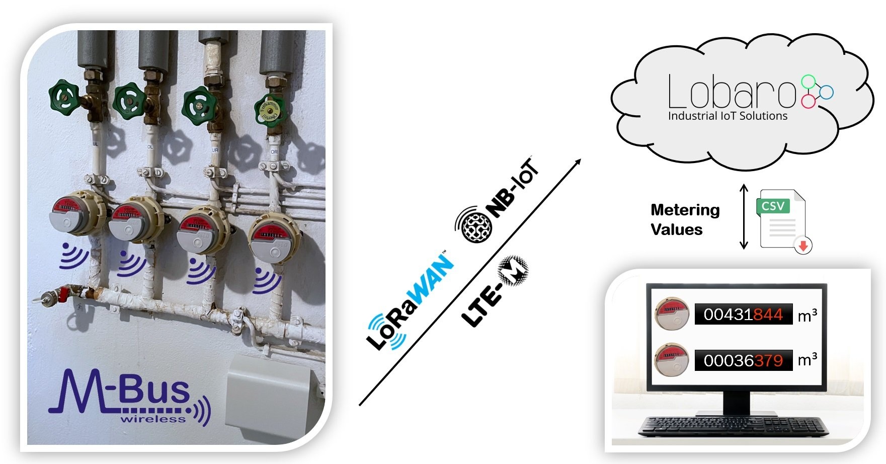
The Lobaro wireless M-Bus gateways collect consumption values from up to 500 commercially available water meters, heat meters, heat cost allocators or similar with 868 MHz wireless M-Bus radio interface or Sensus RF Bubble Up and forward them encrypted via NB-IoT, LTE-M1 cellular radio or LoRaWAN networks for further processing on the Internet.
Forwarded meter values are transmitted, optionally additionally encrypted via DTLS, to a shared or private instance of the Lobaro IoT platform and can be viewed there or downloaded as a CSV file. Alternatively, standardised APIs such as MQTT, HTTP Push, SFTP or a REST interface are available to connect downstream systems or platforms easily and securely. When using LoRaWAN, the Lobaro Platform is optional. When using NB-IoT or LTE-M, on the other hand, it is mandatory. This requirement is explained in the Lobaro IoT Platform FAQ.
Thanks to the new NB-IoT mobile radio, optimised for sensor data, remote reading even works in places such as basements where smartphones have poor or no reception.
Hardware Platforms and Variants
This firmware, following the naming sheme app-nrf9160-wmbus-TZ2-VERSION-HARDWARE, exists in versions targeted for different Lobaro hardware. On all hardware the workflows and functionality is the same. If a certain firmware feature is not available on a specific hardware variant, this will be indicated separately.
LOB-GW-HYB-WMBUS

"Wireless M-Bus Gateway V3"
- Battery driven variant (3.6V D-Cell)
- Example firmware name: app-nrf9160-wmbus-TZ2-0.14.1+hw3
- Lobaro article number: #8000162 + #3000581 (Battery)
LOB-GW-SUN-WMBUS
"Solar Wireless M-Bus Gateway"
- 100% solar powered variant
- Example firmware name: app-nrf9160-wmbus-TZ2-0.14.1+sun
- Lobaro article number: #8000179
LOB-GW-DINRAIL-HYB-WMBUS
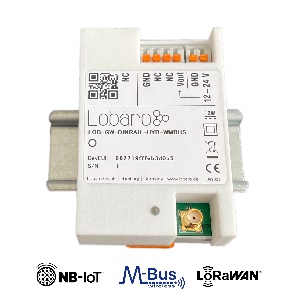
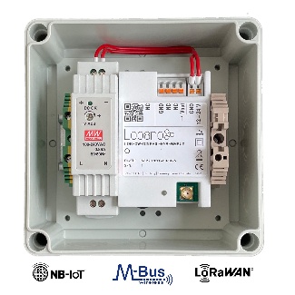
"Wireless M-Bus Gateway (ext. Power, Din-Rail)"
- External 12V-24V powered variant for din-rail mounting
- Example firmware name: app-nrf9160-wmbus-TZ2-0.14.1+dinrail
- Optionally bundled with 230V power-supply and extra shell housing
- Lobaro article number: #8000157 (standalone), #8000158 (bundle)
LOB-GW-WMBUS-NB2
![]()
"Wireless M-Bus Gateway V2" (Discontinued)
- Legacy battery driven variant
- Example firmware name: app-nrf9160-wmbus-TZ2-0.14.1+hw2
- Lobaro article number:
#8000131(discontinued)  LoRaWAN not supported
- DTLS encryption not supported
Basic Workflow
- The gateway remains in power-saving mode most of the time.
- The unit wakes up at flexible configurable time points, e.g. every hours, every 7th day or every Monday.
- Encrypted wireless M-Bus (868 MHz) telegrams are received for a configurable duration and buffered.
- Reception can be limited to certain devices and types by means of filters.
- After the configured collection duration has been reached, the meter data reception is stopped again.
- The buffered meter telegrams get uploaded afterwards on the Internet
- NB-IoT, LTE-M1: Data is send using UDP, DTLS (optional) and CoAP to the Lobaro IoT platform instance.
- LoRaWAN: Data is send as Class A uplinks to the downstream LoRaWAN server / platform on the internet. Metering telegrams may be spliced and send in multiple uplinks.
- The Lobaro Platform can perform decryption the consumption telegrams with stored keys.
- The consumption values are available in table views inside the Lobaro Platform and as a CSV download
- Data may be forwarded from the Lobaro Platform to additional systems and platforms using one of these APIs: MQTT, REST, HTTPS-PUSH or SFTP.
Network Selection Parameters
WAN
This parameter can be used to set whether cellular IoT (NB-IoT, LTE-M) or LoraWAN is to be used for data transmission. With LoRaWAN, the type of network join can also be defined (ABP vs. OTAA).
| Name | Description | Default Value | Value Description & Examples |
|---|---|---|---|
WAN | Technology used for connection and data uplinks to backend. | lte |
|
Compatible wireless meter protocols

- Wireless M-BUS S1, C1 or T1 modes, e.g. unidirectional 868 MHz modes following DIN EN 13757-4.
- Open metering specification (OMS, Annex O): PHY_A - 868 MHz (uplink only)
- Sensus RF Bubble UP - Manufacturer specific radio protocol (Xylem Inc.)
- ME-Funk - Manufacturer specific radio protocol (Müller-electronic GmbH). Decoding of telegrams needs the Lobaro Platform.
![]() 433 MHz variants available on special sales request:
433 MHz variants available on special sales request:
- Open metering specification (OMS, Annex O): PHY_B - 433 MHz (uplink only)
- Sensus RF Bubble UP 433 MHz - Manufacturer specific (Xylem Inc.) radio protocol
Anbindung an das Smart Meter Gateway (SMGW)
Configuration
Lobaro delivers all devices with a reasonable default configuration. Customer specific configurations are possible in different ways:
- Using our free Lobaro Maintenance Tool and the USB PC configuration adapter to be connected to the "config" connector on the hardware. Not accessible in the waterproof version of the Solar Gateway.
- Remotely in the field using LoRaWAN downlink messages.
- Remotely using NB-IoT via the Lobaro Platform.
Remote Configuration
- Devices using LTE-M or NB-IoT can be configured easily using the interface (search for 'config tab' inside devices) in the Lobaro Platform.
- Devices using LoRaWAN can configured by sending downlinks on port 128:
- A single config parameter can be changed by sending
S<parameter>=<value> - For example: changing the device to switch to using LTE-M or NB-IoT, you would change the parameter "
WAN"to "lte"by sending:"SWAN=lte" - Depending on the used LoRaWAN network servers convention you will to encode this string in Base64 as
"U1dBTj1sdGU="or Hex as"5357414e3d6c7465". - AdditionalI Information: LoRaWAN Downlink Configuration
- A single config parameter can be changed by sending
Config Parameters
LoRaWAN
The connection to the LoRaWAN network is defined by multiple configuration parameters. This need to be set according to your LoRaWAN network and the way your device is supposed to be attached to it, or the device will not be able to send any data.
For a detailed introduction into how this values need to be configured, please refer to the chapter LoRaWAN configuration in our LoRaWAN background article.
| Name | Description | Type | Values | Default Value | Version |
|---|---|---|---|---|---|
OTAA | Activation: OTAA or ABP | bool | true= use OTAA, false= use ABP | ||
DevEUI | DevEUI used to identify the Device | byte[8] | e.g. 0123456789abcdef | ||
JoinEUI | Used for OTAA (called AppEUI in v1.0) | byte[8] | e.g. 0123456789abcdef | ||
AppKey | Key used for OTAA (v1.0 and v1.1) | byte[16] | |||
NwkKey | Key used for OTAA (v1.1 only) | byte[16] | |||
SF | Initial / maximum Spreading Factor | int | 7 - 12 | 12 |
|
ADR | Use Adaptive Data Rate | bool | true= use ADR, false= don't | true |
|
OpMode | Operation Mode | string | A= Class A, C= Class C | ||
TimeSync | Days after which to sync time | int | days, 0=don't sync time | ||
RndDelay | Random delay before sending | int | max seconds | ||
RemoteConf | Support Remote Configuration | bool | true=allow, false=deactivate | true | |
LostReboot | Days without downlink before reboot | int | days, 0=don't reboot | 5 | |
payloadFormat | wMBUS Bridge LoRaWAN Payload Format | int | 0= Encoding in ports, 1= prefixed with time, 2= prefixed with time and rssi | ||
loraMaxMsgSize | Max. LoRa msg size before split (Payload Format 0 only) | int | 10-50 (bytes) | 50 |
NB-IoT
wMBUS
| Name | Description | Type | Values | Default Value | Version |
|---|---|---|---|---|---|
listenCron | Cron expression† defining when to rx wMBUS | 0 0/15 * * * *(every 15 minutes) | |||
cmodeDurSec | Duration (Seconds) of C1/T1-mode receive | 0= Do not collect C1/T1 mode | |||
smodeDurSec | Duration (Seconds) of S1-mode receive | 0= Do not collect S1 mode | |||
xmodeDurSec | Duration (Seconds) of Sensus-RF-BUP-mode receive (Xylem) | 0= Do not collect Sensus RF BUP | v2.6.0 | ||
umodeDurSec | Duration (Seconds) of Müller Funk mode receive | 0= Do not collect Müller Funk | |||
mFilter | wMBus manufacturer filter sep. by , e.g. dme,itw | blank= no filter | |||
typFilter | wMBus device type filter e.g. 08,07 for Heat Cost and Water | blank= no filter | |||
devFilter | wMBus id filter e.g. 88009035,06198833 (8 digits) | blank= no filter | |||
ciFilter | wMBus CI-Field filter e.g. 8a,71 (2 hex digits) | blank= no filter | v2.7.0 |
† See also our Introduction to Cron expressions.
LoRaWAN
Uplink Payload formats
After collecting wireless M-Bus telegrams over the air, the Bridge starts uploading data via LoRaWAN. There exist two data formats that are transmitted over different LoRaWAN ports. As LoRaWAN can only transmit very short messages, the message formats contain only data bytes. The meaning of a byte is determined by its position within a message. The following describes the package formats used by the wireless M-Bus Bridge.
M-Bus telegrams can be longer as the maximal size of a LoRaWAN-Message. For this cases, the Bridge needs to split a telegram into multiple pieces and upload it using multiple LoRaWAN-Messages. There are two different methods this is done, according by the Payload Format you set in the Bridge's configuration.
Payload Format 0 is focused on easy reassembly of the pieces. The parts are encoded by port numbers and the data can just be concatenated together. Payload Formats 1 and 2 add additional information to the telegram. They focus on putting as much of a telegram in a single LoRaWAN-Message as possible with respecting the current Spreading Factor.
| Port | PayloadFormat | Message |
|---|---|---|
| 1 | any | Status message |
| 11-99 | 0 | Default PayloadFormat. Part of split telegrams is encoded in Port (e.g. Port 24 = Telegram 2 of 4). |
| 101 | 1 | Data Message without timestamp. Part of split telegrams is encoded in payload. |
| 102 | 2 | Data Message with timestamp. Part of split telegrams is encoded in payload. |
Status Packet (Port 1)
Port 1 - In order to provide some information about the health & connectivity state of the device itself, the device sends a status update at a daily basis. The status packet is sent on the first upload phase after activation of the device (after reboot) and then repeatedly in every upload phase that takes place a day or longer after the previous status packet. It has a length of 7 or 8 bytes. The battery voltages and ambient temperature are encodes as 16 bit integer using little endian encoding.
| name | type | bytes | description | example |
|---|---|---|---|---|
| version | uint8[3] | 0-2 | Version of the firmware running on the device | 1, 5, 1 ≡ v1.5.1 |
| v_bat | uint16 | 3-4 | Battery voltage in mV | 2947 ≡ 2.947V |
| temp | int16 | 5-6 | Temperature measured inside the device in 1/10 °C | 246 ≡ 24.6°C |
| flags | int8 | 7 | Bit 7 (e.g. 0x01) = No wMbus Telegram received (added in v2.5.0) | 0x01 |
Temperature Sensor
The temperature sensor is not present anymore on dedicated V2 hardware, instead 0xffff will be returned.
We provide a JavaScript reference implementation of a decoder for this status packet on GitHub, which can be used directly for decoding in The Things Network.
Data Packet (Port 11-99, PayloadFormat 0) - Default
After each wMBUS collecting phase, all saved telegrams (up to 500 can be stored) will be uploaded via LoRaWAN uplink messages as fast as possible. The received wMBUS telegrams that did pass the configured white list filters will be uploaded without any modification in one or more LoRaWAN messages. If a wMBUS telegram is bigger than the bridge configuration parameter loraMaxMsgSize the transmission will be done using multiple LoRaWAN messages. This parameter is limited to ≤ 50 bytes due to LoRaWANs maximum payload size restrictions. In case of telegram splitting is needed the receiving backend application server as to reassemble the original wMBUS telegram before decryption & parsing of the meter data. This is done by simply joining the messages together in the order of receive. The LoRaWAN port encodes identifies a LoRaWAN fragment of the original wireless M-Bus telegram. This way partial messages can be identified using the LoRaWAN Port:
- 10 < LoRaWAN Port < 100 ≡ (Part Number | Total Parts)
Gaps in the LoRaWAN Frame Counter are giving a hint for missing telegram parts which can happen in LoRaWAN since it's a ALOHA based protocol, e.g. collisions and some packet losses are accepted by principle of operation. In case the backend noticed a missing packet the wMBUS telegram can't be assembled anymore as described before.
Examples
Examples (with loraMaxMsgSize = 50):
- A 48 Byte wMBUS telegram will be send on LoRaWAN port 11. Port 11 says it is the first message of only one message (no splitting).
- A 75 byte wMBUS telegram will be send in two messages on LoRaWAN ports 12 and 22. Port 12 means this part one of a wMBUS telegram that got splitted into two LoRaWAN messages. Port 22 means that this data is the 2nd part of the original wMBUS data. Both parts have to been concatenated in the order of receive by the backend.
- A 101 byte wMBUS telegram will be send in three messages on LoRaWAN ports 13, 23 and 33. Port 13 means this part one of a wMBUS telegram that got splitted into three LoRaWAN messages. Port 23 means that this data is the 2nd part of the original wMBUS data. Port 33 means that this data is the 3rd part of the original wMBUS data. All three parts have to been concatenated in the order of receive by the backend.
Data Packet without Timestamp (Port 101, PayloadFormat 1)
When using Payload Format 1, collected telegrams are uploaded on a single Port: 101. For each telegram there will be added the timestamp of reception. The first byte of messages on Port 101 encodes splitting of messages as follows.
Splitting
Every Uplink on Port 101 is prefixed with a single byte, where the least significant Bit indicates if that Uplink is the first part of a message, and the second least significant Bit indicates if that Uplink is the last part or a message. So there are 4 different possible values for the first Byte of an Uplink on Port 101:
| Value | Meaning |
|---|---|
0x03 | This Uplink is both first and final part of a message. So the remaining Bytes in this Uplink contain the whole message. |
0x02 | This Uplink is the last but not the first part of a message. There has been at least one Uplink before this one, that contained data that needs to be prepended to the current Uplink in order to get the full Message |
0x01 | This Uplink is the first but not the last part of a message. There follows at least one Uplink that contains more data to be appended to the current's data in order to get the full message. |
0x00 | This Uplink is neither first nor last part of a message. There has been at least one Uplink before this one that contains more data of the current Message, and there follows at least one more Uplink with data for this Message. |
So each message sent on Port 101, whether it is contained in a single Uplink or spread over multiple ones, starts with an Uplink where the least significant Bit of the first Byte is set. Each Message ends with an Uplink where the second least significant Bit of the first Byte is set. In cases where the Message fits in a single Uplink, that Uplink is both first and last Uplink, and therefore both Bits are set.
The combination of those two Bits and the Frame Counter of the Uplinks makes it possible to upload Messages of any length while allowing the receiving side to now exactly, if a Message has been transferred completely, or if part of it is missing (when there are Frame Counter values missing).
The Bridge puts as many Bytes in each Uplink as possible for the current Spreading Factor, even if the Spreading Factor changes between Uplinks because of ADR.
When the data of all Uplinks that are part of a single Message are appended in order of reception (after removing the first Byte of each Uplink), you get the payload Data of a full message.
Payload (Format 1)
The Payload Data after reassembly of the split parts consists of a 5 Byte Timestamp, that marks the point in time the Bridge did receive that telegram, followed by the Data of the Telegram. The Timestamp follows the convention of all our 40bit-Timestamps; you can find the details under Timestamp in our LoRaWAN Background Information.
Examples
For easier understanding, the wMBus-Telegram in the examples will always be 0102030405060708090a0b0c0d0e0f.
# An Uplink of 21 Bytes on Port 101:
'03005e53f31a0102030405060708090a0b0c0d0e0f'
# Analised:

'03' -> First and Last Uplink of Message -> complete Message in this Uplink

'005e53f31a' -> Unix Timestamp 1582560026 -> 2020-02-24T16:00:26 UTC

'0102030405060708090a0b0c0d0e0f' -> wMBus Telegram
# An Uplink of 11 Bytes on Port 101, Frame Counter 341:

'01005e53f31a0102030405'

'01' -> First Uplink of Message, more Uplinks follow

'05e53f31a0102030405' -> First Part of Message Data.

# Another Uplink of 11 Bytes on Port 101, Frame Counter 342:

'02060708090a0b0c0d0e0f'

'02' -> Last (but not first) Uplink of Message.

'060708090a0b0c0d0e0f' -> Second and final Part of Message Data.

# We Received a 'first' Part with Frame Counter 341 and a 'last'

# Part with Frame Counter 342, so we know we did not miss any

# Parts in between. We can now assembly the complete payload:

'05e53f31a0102030405060708090a0b0c0d0e0f'

# Payload anaylsed:

'005e53f31a' -> Unix Timestamp 1582560026 -> 2020-02-24T16:00:26 UTC

'0102030405060708090a0b0c0d0e0f' -> wMBus Telegram
# An Uplink of 8 Bytes on Port 101, Frame Counter 519:

'01005e53f31a0102'

'01' -> First Uplink of Message, more Uplinks follow

'05e53f31a0102' -> First Part of Message Data.

# Another Uplink of 8 Bytes on Port 101, Frame Counter 520:

'0003040506070809'

'00' -> Middle Part of Message, there have been some Parts already, more Uplinks follow

'03040506070809' -> Second Part of Message Data.

# Another Uplink of 7 Bytes on Port 101, Frame Counter 521:

'020a0b0c0d0e0f'

'02' -> Last (but not first) Uplink of Message.

'0a0b0c0d0e0f' -> Third and final Part of Message Data.

# Frame Counters are consecuetive, so the complete Message is:

'05e53f31a0102030405060708090a0b0c0d0e0f'
# An Uplink of 8 Bytes on Port 101, Frame Counter 123:

'01005e53f31a0102'

'01' -> First Uplink of Message, more Uplinks follow

'05e53f31a0102' -> First Part of Message Data.

# Another Uplink of 7 Bytes on Port 101, Frame Counter 125:

'020a0b0c0d0e0f'

'02' -> Last (but not first) Uplink of Message.

'0a0b0c0d0e0f' -> Third and final Part of Message Data.

# Frame Counter indicates, that a Part in the middle is missing,

# so we have to drop the Message.
Data Packet with Timestamp (Port 102, PayloadFormat 2)
Upload Format 2 works like Upload Format 1, with the same logic for splitting messages, but uploads are sent on Port 102. The Payload consists of a 5 Byte Timestamp marking the time of reception, followed by a uint_8 that holds the (negated) RSSI value for that reception, followed by the Data of the Telegram.
Examples
# An Uplink of 22 Bytes on Port 102:

'03005e53f31a3f0102030405060708090a0b0c0d0e0f'

# Analised:

'03' -> First and Last Uplink of Message -> complete Message in this Uplink

'005e53f31a' -> Unix Timestamp 1582560026 -> 2020-02-24T16:00:26 UTC

'3f' -> 63 -> RSSI of wMBus reception = -63

'0102030405060708090a0b0c0d0e0f' -> wMBus Telegram
Upload Speed / DurationThe bridge has to work in compliance with the European SRD 868 1% duty-cycle regulations. This implies as a rule of thumb the device can upload at most wMBUS telegrams via LoRaWAN for 36 seconds every hour.
The actual transmit time ('ToA: time on air') for each LoRaWAN message depends on the byte size and the used LoRa spreading factor (SF) which defines how redundant LoRa data is send. This means a device with good connectivity and consequently using LoRa SF7 (ToA ≤ 0,050s) can upload much faster more data than a node using LoRa SF11 (ToA ≥ 1s) due to a hard to reach LoRaWAN gateway. The bridge will upload in conformity with the regulations automatically as fast as possible. When it has to wait it enters a low power sleep mode until the next transmission is possible again. The next data collection phase will be started only after completion of the previous upload phase in respect to the configured listenCron parameter. Because of this it is advisable to define the cron parameter with an estimation of the upload duration in mind. This will avoid unexpected 'skipping' of data collection phases.
Downlinks
| Port | Message |
|---|---|
| 128 | Remote Confiuration |
| 132 | wMbus Bridge Commands |
Remote Configuration (Port 128)
Update of Configuration parameters is documented in our LoRaWAN downlink messages documentation.
Supported downlink messages:
| Char | Command | Parameter | Hex | Version required |
|---|---|---|---|---|
? | Request firmware and version | None | 3F | |
g | Get config parameter value | <name> | 67 | |
r | Reset config parameter value | <name> | 72 | |
s | Set config parameter value | <name>=<value> | 73 | |
| S | Set config parameter value + Save and reboot | <name>=<value> | 53 | ??? |
a | Append to config parameter value | <name>=<value> | 61 | |
b | Reboot device without saving | None | 62 | |
w | Save config and reboot device | None | 77 |
<name> is the ASCII encoded name of the parameter
- <value> is the ASCII encoded value
wMbus Bridge Commands (Port 132)
| Port | Action | FW Version | Payload (ASCII) | Payload (Hex) | Payload Base64 |
|---|---|---|---|---|---|
| 132 | Ad-hoc readout | > 2.4.0 |
| 72656164 | cmVhZA== |
Ad-hoc readout
A downlink that triggers an Ad hoc readout, independent of CRON triggers. The Ad-hoc readout is using the same parameters (filters and listening duration) as a CRON triggered readout.
Decoding wMBUS telegrams
After receiving the raw wireless M-Bus telegrams from your LoRaWAN network provider the actual metering data has to be decrypted and decoded by a backend service for further processing. The details of this are described in the EN 13757 norm and the newer OMS specification, which is a clarification of the original underlying norm.
A universal wireless M-Bus decoder is a relatively complicated piece of software if you start implementing it from scratch since the norm covers many different use cases, units, meter types and data formats. If you know in advance the exact telegram format of the deployed meters in your setup a hard coded data decoding may be a feasible approach. This is because wireless M-Bus devices often send the same telegram format in every transmission. Please contact the manufacturer of your meters for the needed telegram format details.
An an alternative to support a quick evaluation of our hardware Lobaro offers a easy to use webservice which is designed to decode all sorts of wMBUS input data including decryption if the correct key has been provided. You can access the decoder service for free during testing. The API can be licensed for production usages.
Free online wMBUS decoder (for testing)
Your meter fails to parse correctly?
Since wireless MBUS is a complex and grown specification some meters may fail to decode correctly. We try to fix any decoding issues as quickly as possible if you report us problems with your specific wMBUS device.
Example Parser
TTN / Chripstack / Lobaro Platform / niota (see wrapper functions)
function readVersion(bytes, i) {
    if (bytes.length < 3) {
        return null;
    }
    return "v" + bytes[i] + "." + bytes[i + 1] + "." + bytes[i + 2];
}

function Decoder(bytes, port) {
    // Decode an uplink message from a buffer
    // (array) of bytes to an object of fields.
    var decoded = {};

    if (port === 9) {
        decoded.devStatus = bytes[0];
        decoded.devID = bytes[1] | bytes[2] << 8 | bytes[3] << 16 | bytes[4] << 24;
        decoded.dif = bytes[5];
        decoded.vif = bytes[6];
        decoded.data0 = bytes[7];
        decoded.data1 = bytes[8];
        decoded.data2 = bytes[9];
    }

    // example decoder for status packet by lobaro
    if (port === 1 && bytes.length == 9) { // status packet - old
        decoded.FirmwareVersion = String.fromCharCode.apply(null, bytes.slice(0, 5)); // byte 0-4
        decoded.Vbat = (bytes[5] | bytes[6] << 8) / 1000.0; // byte 6-7 (originally in mV)
        decoded.Temp = (bytes[7] | bytes[8] << 8) / 10.0; // byte 8-9 (originally in 10th degree C)
        decoded.msg = "Firmware Version: v" + decoded.FirmwareVersion + " Battery: " + decoded.Vbat + "V Temperature: " + decoded.Temp + "°C";
    } else if (port === 1 && bytes.length >= 7) {
        decoded.FirmwareVersion = readVersion(bytes, 0); // byte 0-2
        decoded.Vbat = (bytes[3] | bytes[4] << 8) / 1000.0; // originally in mV
        decoded.Temp = (bytes[5] | bytes[6] << 8) / 10.0; // originally in 10th degree C
        decoded.msg = "Firmware Version: " + decoded.FirmwareVersion + " Battery: " + decoded.Vbat + "V Temperature: " + decoded.Temp + "°C";
        if (bytes.length == 8) { // added in v2.5.0
            decoded.Flags = bytes[7];
        }
    }

    return decoded;
}

// Wrapper for Lobaro Platform
function Parse(input) {
    // Decode an incoming message to an object of fields.
    var b = bytes(atob(input.data));
    var decoded = Decoder(b, input.fPort);

    return decoded;
}

// Wrapper for Loraserver / ChirpStack
function Decode(fPort, bytes) {
    return Decoder(bytes, fPort);
}

// Wrapper for Digimondo niota.io
// Uncomment only when used in niota!
/*
module.exports = function (payload, meta) {
    const port = meta.lora.fport;
    const buf = Buffer.from(payload, 'hex');

    return Decoder(buf, port);
}*/