Modbus Gateway with external power supply. Upload data via NB-IoT, LET-CatM1, LoRaWAN or LAN.

Support for Modbus ASCII, RTU (RS-485) and additionally TCP/IP on external powered din-rail variant.
The current Firmware does not support Modbus TCP or LAN/Ethernet connections, yet. Some features will be implemented in a future release and do not work yet. LoRaWAN Class C is currently not supported.
| Model | LOB-GW-DINRAIL-HYB-MODBUS |
| Order number |
|
|
|
|
8000159 - Hybrid Modbus Gateway (ext. Power, Din-Rail) Including: Antenna | 8000166 - Hybrid Modbus Gateway (ext. Power, 230V) Including: Antenna, 2x cable feedthrough | 8000171 - Hybrid Modbus Gateway V2 (Battery) |
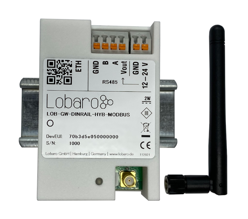
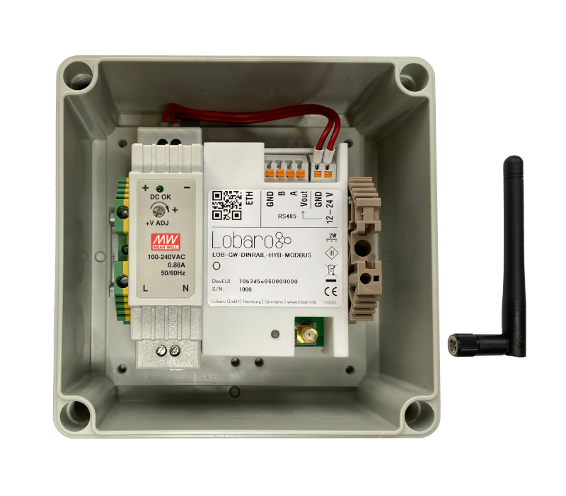
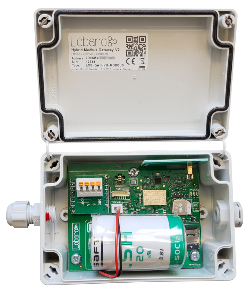
Table of Content
Overview
The Lobaro Hybrid Modbus Gateway is a simple to use, cost and energy efficient device that reads, caches and forwards data via Modbus from any number of Modbus enabled devices into the Internet.
The Gateway can be used to communicate with Modbus Slave devices (ASCII/RTU on a RS-485 bus, TCP on over Ethernet) over NB-IoT, LTE-CatM1, LoRaWAN or LAN. Modbus commands can be transmitted via Downlink message to the Gateway and are forwarded by the Bridge to the connected Slave Devices. Received responses are forwarded as Uplink messages to the Lobaro IoT Platform. The Modbus Gateway can also be configured to execute Modbus commands regularly and report the responses at time of execution.
The Modbus Gateway supports reading of all four object types that can be provided by Modbus slave devices: Coil, Discrete Input, Input Register, and Holding Register. It also supports writing values to all writable objects: Coils and Holding Registers. Multiple different slave devices on the Bus can be accessed individually by a single Gateway device, even if the slave devices have a different Modbus configuration. Reading intervals and register definitions can be configured very flexibly to suit individual requirements.
Quick start guide
For details about each Steps please refer to the related detailed sections of the Manual below.
- Make sure the SIM card is inserted correctly when using NB-IoT or LTE-CatM1.
- Connect the Modbus Gateway to your Modbus Slave Devices
- Via RS485 connector using a twisted pair cable:
AtoA,BtoB, andGNDtoGND(GNDis not strictly necessary but enhances the connection. Not all slave devices supply aGNDconnector). - Via ETH connector for Modbus TCP using a RJ45 LAN cable(externally powered variants only).
- Via RS485 connector using a twisted pair cable:
- Connect the Modbus Bridge to a computer using the Lobaro Configuration Adapter and the Lobaro Maintenance Tool.
- Connect power to the device - powering with the configuration adapter does not work.
- Make sure the configuration is correct to connect to the Internet (depends on you connection method: Mobile, LoRaWAN or LAN.
- Make sure the configuration is correct to read out your desired Modbus device (e.g. ASCII/RTU, Baud, Data Length, Stop Bits, Parity and Modbus Command).
- Optionally: Switch to the Log tab of the Lobaro Tool to see if the device is connecting and working as expected.
- Go to The Lobaro Platform and log into your account.
- Go to "Devices" and select your "Hybrid Modbus Gateway".
- If you have several Gateways: the "Address" is printed on the device's case as "DevEUI".
- You should see all Uplinks the Gateway collected sent far. Next step is to configure your individual Device Type to display you slaves data or forward data to your own IT.
Supported Devices
The Lobaro Modbus Gateway works with all devices that act as a Modbus Client using RTU, ASCII (or, in a future release TCP). Some devices that have been used successfully with the Gateways are:
Device | Type | Manufacturer | More information | Sample Implementations |
|---|---|---|---|---|
| Octave Ultrasonic Meter | Water meter | Arad Group | External Link | |
| ECL Controller | Heat/Hot Water Regulation | Danfoss | External Link | |
| UMD 97 | Smart Grid Power Meter | PQ Plus | External Link (German) | |
| DRS458DE | Power Meter | B+G E-Tech GmbH | External Link | |
| Feuchtemessumformer PCE-P18 Modbus RTU | Humidity / Temperature sensor | PCE-Intruments | External Link (German) | |
| Lobaro Pressure Sensor | Pressure Sensor | Lobaro | Sample Implementations |
Modbus Introduction
For an overview about the Modbus protocol please refer to our documentation page about Modbus.
For a deeper introduction into Modbus please visit https://en.wikipedia.org/wiki/Modbus, which is a good place to start.
Please be aware that to configure the Gateway correctly, you will need to know the details of your installation and the slave devices you are trying to connect. Debugging a failing Modbus setup is quite complex, as there are many potential errors that cause the problems.
Please also note that even when you succeed in reading the data you need from the correct registers, neither the Gateway, nor the Lobaro Platform can know, what that data means. There is no semantic defined in Modbus; without additional information, the data is just bytes, that need to be interpreted by custom software. Registers can hold boolean values, signed or unsigned integers, floating point numbers or anything else. Often values span over multiple registers (each register holds exactly 2 bytes, so that e.g. 32bit integers will need two registers. There is also no dedicated byte order for Modbus, so that is not even trivial to read integers. This is a problem that is intrinsic to using Modbus and cannot be solved easily by a generic bridge device.
If you need support for creating a custom parser that processes the Uplinks and convert it to an easy to use format, please contact us, so that we can send you an offer for your individual use case.
Setting up the device
Interfaces
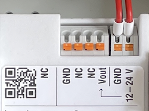
Connections as on the label:
- Vin - Supply voltage 12 - 24 Volt DC
- GND - Ground
- Vout - same as Vin
- A - Modbus ASCII/RTU line
- B - Modbus ASCII/RTU line
- GND - Ground
- ETH - Ethernet connection for LAN Uplink or Modbus TCP
- Connected cables must be between 0.05 mm² (AWG30) and 1.31 mm² (AWG16).
- Inserted cable length must be between 6mm and 7mm.
- Recommended wire termination:
- Weidmüller: H0,14/10 GR SV, Article No.: 9005180000, 8mm/6mm, max. AWG26
- Cables must not be connected or disconnected while the device is powered.
- Vout only supports small consumers like sensors with ≤ 1W. If in doubt, connect sensors to a dedicated power supply according to their manufacturer's instructions.
Power Supply
- Power supply via external mains adapter with 12 - 24 Volt DC
- Power output must be at least 2W and maximum 100W.
Radio (LoRa, FSK, NB-IoT, LTE Cat-M1)
|
|
|
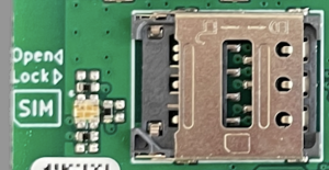
| Female SMA Connector | Antenna | Nano SIM (4FF) for mobile connectivity |
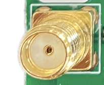
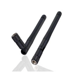
The antenna is used for different radio technologies based on LoRa, FSK including LoRaWAN® and wireless MBUS S1, C1/T1 Modes (868 MHz), OMS v3 & v4.
The same antenna is also used for communication via NB-IoT and LTE Cat-M1. A Nano SIM (4FF) is required for mobile connectivity.
The SIM Card must not be inserted or removed while the device is powered.
Properties of compatible SMA Antennas:
| SMA Joint Rod Antenna (LTE, LoRa) | |
|---|---|
| Frequency range | 698-960 / 1710-2700 MHz |
| Length | 108 mm |
| Antenna Gain | 2 dBi |
| V.S.W.R | <= 2.5 |
| Radiation | Omnidirectional |
| Polarisation | Vertical |
| Max. Power | 5 W |
| Impedance | 50 Ohm |
| Connector | SMA Male |
| Material of dome | TPE |
| Lobaro Article No. | 3000413 |
The device was only tested with the listed antenna. Lobaro does not take liability for use with different antennas.
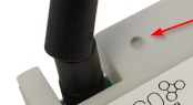
RESET-Button
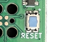
- Press the RESET Button to restart the device
- The RESET Button can be pressed through a small hole in the cover (e.g. with a paper clip). The position is marked with a ring on the label.
Config Port
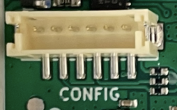
- The config port can only be reached when the cover is removed
- The configuration port is compatible with our 6-pin Lobaro USB Configuration Adapter (Article No. 8000005).
- A free to use configuration tool can be downloaded from the Lobaro website.
LED
- Status information is visualized via the RGB LED
Mobile operator and LTE band configuration
If you are using a different mobile operator than pre-configured, you should change the mobile operator code set in the Config Parameters Operator and (LTE) Band Operator codes are 5 digit codes that indicate country and operator.
For details about configuration for mobile network operation please refer to our article about Mobile Network Connection
Configuration
The device is shipped with default configuration parameters. The configuration can be changed via the 6-pin config port using the Lobaro USB Configuration Adapter.
More information about the usage of the configuration tools can be found in our documentation.
Remote Configuration is also supported after initial network connection.
Networking Parameters (NB-IoT / LoRaWAN)
| Name#LoRaWAN-RemoteConfiguration | Description | Default Value | Value Description & Examples |
|---|---|---|---|
WAN | Radio technology used for connection to backend | lte |
|
Host | Hostname / IP of the Lobaro Platform API Not used for LoRaWAN uplink | 94.130.20.37 | 94.130.20.37 = platform.lobaro.com |
Port | Port number of the Lobaro Platform API Not used for LoRaWAN uplink | 5683 |
NB-IoT Parameters (WAN = "lte", "nbiot", "ltem")
The LTE functionality is enabled if the WAN parameter is set to lte, nbiot, or ltem. Using this mode requires an appropriate SIM-Card to be inserted.
| Name | Description | Default Value | Value Description & Examples |
|---|---|---|---|
Operator | Mobile Operator Code (optional) | 26201 | 26201 (=Deutsche Telekom), for other operators, see above. |
Band | NB-IoT Band | 8 | "8", "20", "8,20", Empty = Auto detect (longer connecting time) |
APN | Mobile operator APN (optional) | iot.1nce.net | 1nce: iot.1nce.net Vodafone Easy Connect: lpwa.vodafone.com (l = littel L) |
PIN | SIM PIN (optional) | Empty or 4 digits (e.g. 1234) |
LoRaWAN Parameters (WAN = "lorawan", "lorawan-abp")
| Name | Description | Default Value | Value Description & Examples | Since |
|---|---|---|---|---|
DevEUI | DevEUI used to identify the Device | Device's own DevEUI as printed on label | 8 bytes = 16 hex digits, e.g. 0123456789abcdef | |
JoinEUI | EUI used for OTAA (aka AppEUI) | Individual default value for each device | 8 bytes = 16 hex digits, e.g. 0123456789abcdef | |
AppKey | AES Key used for LoRaWAN | Individual default value for each device | 16 bytes = 32 hex digits, e.g. 0123456789abcdef001122334455667788 | |
SF | Minimal Spreading Factor used | 12 | 7-12, used after reset, can be decreased by ADR during operation (but not increased) | |
OpMode | LoRaWAN Operation Mode | A | A = Class A, C = Class C | v0.2.1 |
Keep the value of AppKey secret. If you change it, make sure you are using a good random source.
OTAA - Over the Air Activation
The preferred method to use LoRaWAN is Over The Air Activation (OTAA). When WAN="lorawan" the device uses the values to perform an OTAA Join with the LoRaWAN Network Server. Make sure the values for DevEUI, JoinEUI, and AppKey match.
The device is manufactured with a globally unique EUI64 that is used as DevEui. This EUI is printed on the devices label and can be used to identify a device. You can change the DevEUI used for LoRaWAN by changing the configuration parameter DevEUI. The device will still keep it's unique EUI64 it was delivered with. You can see it in the Log output during booting, even if a different value is used for the DevEUI.
Each Device will be configured with a unique JoinEUI and AppKey that are generated using a cryptographic hashing algorithm. Those values will seem random and are very likely to be unique for each device. These values are known to Lobaro but will not be made public. You can change the AppKey if you prefere to have Keys that are known only to you. Be sure to use a good random source when generating keys.
ABP - Activation by personalisation
Our devices support activation by personalisation (ABP) when WAN="lorawan-abp". This mode is useful for devices that have a bad reception. You will have to synchronise session keys by hand between the device and your Network Server when using ABP.
When using ABP, the device will use the parameters DevEUI and AppKey for generating the session parameters:
DevAddrwill consist of the last for bytes ofDevEUINetSKeywill be cryptographically derived fromAppKeyAppSKeywill be cryptographically derived fromAppKey
The Values will be printed out in the Log after boot, so you can copy them to the configuration in your Network Server. Do change the DevAddr, alter the DevEUI value in the configuration. To create a different pair of session keys, change the value of AppKey in the configuration. Best practise is, to change it to randomly generated bytes coming from a good random source. The generated Session Keys will be deterministic for a given value of AppKey, even if used on different devices.
LAN Parameters (WAN = "lan")
Connection via LAN/Ethernet is not supported, yet.
Coming soon!
Modbus related Parameters
| Name | Description | Default Value | Values Description & Examples |
|---|---|---|---|
MbCmd | List of Modbus Commands with Cron and Modbus parameters (see below). | 0 0/5 * * * *:R,9600,8N1:010300000003 | One or more entries of Modbus commands to be executed by the device. Each entry starts with a Cron expression defining when to execute the commands followed by the bus parameters used to address the Modbus slave devices. Each entry can contain multiple commands. See description below for a detailed explanation. † |
† See also our Introduction to Cron expressions.
MbCmd defines, what Modbus commands are executed on the Bus, when, and what Modbus Configuration to use for them. The configuration is very flexible and allows complex setups, that include executing different commands at individual intervals or times or using multiple different Modbus parameters to address incompatible Slaves on the same installation. Any Modbus command can be sent, including writing registers or diagnostic messages.
The command is entered in Hex and without any check sums and is 6 bytes long (12 hexdigits). The default value is 010300000003, it consists of 4 hex parts: 01, 03, 0000, 0003
0x01
Address of the Slave Device. 1 byte: often 01 new devices
0x03
What kind of Modbus Register to read. 1 byte. 03 stand for Holding Register.
0x0000
Number/address of the first register to read. 2 bytes. Many devices have some value to read out at 0000.
0x0003
Number of consecutive registers to read from the first register. 2 bytes. This would read the registers #0, #1, and #2 in one command.
The default value of 0 0/5 * * * *:R,9600,8N1:010300000003 shows a very basic example with a single entry executed every 5 minutes using Modbus RTU to read 3 consecutive holding registers from a single slave device.
The parameter consists of up to 32 entries, separated by semicolons. Each entry consists of three parts, separated by colons: its individual Cron expression, the Modbus configuration used, and the Modbus commands to be executed. Each entry can have multiple Modbus commands to execute on activation, separated by comma. A Modbus command must be written as the Bytes to be sent on the bus in Hex notation. The check sums will be added by the device according to the protocol used.
MbCmd        = "<Entry1>;<Entry2>;...;<Entry32>"
Entry        = "<Cron>:<MbParm>:<Command1>,<Command2>,...,<CommandN>"
MbParm       = "<Protocol>,<Baud>,<SymbolCfg>"
Protocol     = "R" for Modbus RTC, "A" for Modbus ASCII
Baud         = Baud rate, any of: 2400, 4800, 9600, 19200, 38400, 57600, 115200
SymbolConfig = Token string defining Data Length, Parity, and Stop Bits. Any of: "7E1", "7E2", "8N1", "8N2"
Command      = "<bytes to be sent in hex without checksum>"
Examples
Example A:
"0 0/5 * * * *:R,9600,8N1:010300000003"
  Entry 1:
    Cron:   "0 0/5 * * * *": Execute entry every 5 minutes, on minutes 0, 5, 10, 15, ..., 55
    Config: "R,9600,8N1": Use Modbus RTU on 9600 Baud, Datalength: 8, Parity: None, 1 stop bit
    Commands:
      "010300000003": Read 3 holding registers of Slave 1, starting at register 0

Example B:
"0 * * * * *:A,9600,7E1:0e0400100004,0f400100004;0 0 * * * *:A,9600,7E1:0e0400200020"
  Entry 1:
    Cron:   "0 * * * * *": Execute entry every full minute
    Config: "A,9600,7E1": Use Modbus ASCII on 9600 Baud, Datalength:7, Parity: Even, 1 stop bit
    Commands:
      "0e0400100004": Read 4 input registers of Slave 14, starting at register 16
      "0f0400100004": Read 4 input registers of Slave 15, starting at register 16
  Entry 2:
    Cron:   "0 0 * * * *": Execute entry every full hour
    Config: "A,9600,7E1": Use Modbus ASCII on 9600 Baud, Datalength:7, Parity: Even, 1 stop bit
      "0e040a800020": Read 32 input registers of Slave 14, starting at register 2688
Modes of operation (work cycle)
Subject to change! This product is still very young and experience might lead to adjustments in the future.
This chapter explains how the device starts and works to collect and upload data.
Startup process
The starting process of the device is linear and executed the following steps in the order given here. The startup is triggered on power on or after a reset was triggered; this can happen over the reset button, by using the Lobaro tool over the config adapter, by sending a reboot command via Downlink, of if a fatal error occurs during operation of the device.
- On power on (or after a reset), the device will start by verifying the signature of the installed firmware. It will only continue the boot process if the signature is valid.
- The device will then activate the Arm TrustZone of its central processor, to prepare an isolated environment for the actual firmware to run. This activates hardware security mechanisms that protect the device from a wide range of errors and manipulations while it is running.
- Only then, the application program is started, having restricted access to the hardware.
- The application reads and outputs the configuration parameters programmed into it and verifies the configuration does not contain any obvious errors (like invalid syntax or impossible value combinations). If any fatal errors exist, the device will output information about it in the Log and then reboot, so that you spot invalid configurations directly when you set them.
- At this point the RGB-LED starts to continuously output the state of the Modbus connection and the connection to the backend.
- The device will try and execute every Modbus command from every entry in the configuration parameter
MbCmd, using the Modbus configuration of the entry (writing operations are skipped to avoid side effects). This allows you to check your Modbus configuration and the connection to the slave devices early on boot and even without a config adapter attached. The device will continue execution, even if the Modbus Commands fail, so that you can check the connection to the backend even when not connected to the Modbus slaves. - After testing Modbus, the device will try to connect to the network for connection to the backend. The exact action will depend on your configuration:
- For NB-IoT or LTE-M the Gateway will activate its Modem and try to attach to the mobile provider. If that succeeds, it will try to connect to the backend configured (normally an instance of the Lobaro Platform). If that succeeds, the device will upload some information about itself to the backend (including its configuration) and than synchronise its internal clock over the connection. Only if all this succeeds, the device will move on.
- For LoRaWAN with OTAA, the device will perform an OTAA Join operation with the LoRaWAN Network Server. If that succeeds, the device will upload a Status Message that will also be used to synchronise its internal clock with the network. Only if that succeeds, the device will move on. On failure, the device will retry with increasing timeouts to perform the join operation and time sync, until it succeeds.
- For LoRaWAN with ABP there is no explicit joining operation, as the session must already exist between Network Server and Device. It simply uploads a Status Message that will also be used to synchronise the internal clock. If the synching fails multiple times, the device will skip synchronisation and just move on to start normal operations. Be aware that this can lead to the Device operating with a clock that does not match real time. The Modbus Commands will be executed according to that clock, which will most likely not be consistent with what you expect. This exception is introduced on purpose, as ABP is meant to make the device usable in locations, where there is poor Downlink reception from the Network, where an OTAA Join cannot be performed, but Uplink messages still might be coming through to the Network. The device will continue to try and synchronise its clock every day and might succeed at some point in the future. The changing of the clock will be compensated as well as possible, but the exact times when commands are executed is most likely to change at that point.
- When the connection to the backend has been established (this is not certain to have succeeded when using LoRaWAN ABP), the device will start its internal scheduler and will from this moment on be running in normal operation mode.
Normal operation
The actions executed by the device during normal operation are controlled by a scheduler that executes a list of jobs whenever it is their time to run. Only a single job will be executed at any time, so if a job is running for some time, other jobs will be executed delayed (but the execution will not be skipped). Each entry you add to the MbCmd config parameter will have its own job in the scheduler. The Cron Expression of the entry will control, how often and when the job will be executed. In addition to that there will be a Status job which runs once every day and triggers the upload of a status message which will also perform a clock synchronisation. When your configuration has multiple entries that are scheduled for the same time, they will be executed in the order you put them in the configuration.
The jobs will generate Uplink messages that need to be uploaded. Those will be queued and upload in the order they are generated. The device will continue to execute jobs while handling uploads. When Uplinks are generated faster than they can be sent, the queue will run full and new Uplinks will be dropped silently. This is most likely to happen when using LoRaWAN on higher spreading factors, as the Gateway can read data over Modbus much faster than it can be sent over LoRaWAN.
After each Uplink sent, the device will look for Downlinks coming from the Network (this is done for both, LoRaWAN and LTE configurations). Downlinks can contain remote commands controlling the device (like configuration changes, reboot requests, or (for LTE only) remote firmware updates). There can also be Modbus commands sent via Downlink that will be executed on the bus by the Gateway directly (the response from the slave will be sent as Uplink). Downlink Modbus commands are currently only supported for LoRaWAN.
The daily Status message Uplink makes sure that the device can be reached for remote configuration within 24 hours, independent of the current configuration.
Changing configuration or performing a firmware update will result in the Gateway rebooting. We try our best to keep our devices from ever reaching a state that makes them unreachable. A new configuration set via Downlink will be temporary until a connection to the Network can be established again. If the new configuration fails to connect to the Network, the previous configuration is restored.
Mobile data consumption
Uploading one Uplink with 400 bytes including all metadata (might be less, depending on the configuration).
| Telegram upload interval | Monthly NB-IoT data usage |
|---|---|
| 1 each Day | ~12 kB |
| 8 each Day (every 3h) | ~100 kB |
| 400 each Week | ~700 kB |
| 250 each Day | ~3 MB |
All calculations are estimations and might vary depending on the configuration
The Lobaro Platform
The easiest way to work with the Lobaro Modbus Gateway is the Lobaro Platform. You can find it under https://platform.lobaro.com – Log in with the credentials provided by Lobaro.
Your Gateways should be listed under "Devices". If you have multiple devices in your account, you can distinguish them by the field "Address". The Address is printed on the box of the Gateway (the Address is the IMEI of the modem used by the device; that is the unique hardware address used for mobile communication).
Data messages
Data messages differ between LoRaWAN and LTE/LAN upload. While LoRaWAN messages are defined by Port and Byte pattern, LTE/LAN Uplinks are encoded as structured data (CBOR).
Since LoRaWAN Uplinks are limited to ~50 Bytes some information that are available on other transport might be skipped.
Coming soon!
For now please refer to our Modbus LoRaWAN Bridge - We try to keep the payloads similar.
LoRaWAN Payload formats
The Modbus Bridge sends two different kinds of messages over different LoRaWAN ports:
Direction | Port | PlFmt Value | Message |
|---|---|---|---|
| Uplink | 1 | any | Status messages. |
| Uplink | 3 | 1 | Modbus Responses triggered by configuration. |
| Uplink | 4 | any | Modbus Responses triggered by Downlinks. |
| Uplink | 5 | any | Continuation of Responses that do not fit in a single Uplink. |
| Uplink | 20 | 4 | Compact payload format with timestamp |
| Uplink | 20 | 5 | Compact payload format without timestamp |
| Uplink | 128 | any | Remote configuration response |
| Uplink | 129-131 | any | Remote configuration long response 129 = start, 130 = middle, 131 = last |
| Downlink | 4 | any | Modbus Commands to be forwarded by the Bridge. |
| Downlink | 128 | any | Remote configuration |
Uplink Messages
Status message (Port 1)
The Modbus Bridge sends a status messages report on the health of the device itself. This messages are sent along when the device is sending data packages with a maximum of one status message per day.
Status messages are transmitted on port 1 and have a fixed length of 16 bytes.
name | pos | len | type | description | example |
|---|---|---|---|---|---|
| version | 0 | 3 | uint8[3] | Version of firmware running on the device | [0, 4, 1] ≡ v0.4.1 |
| flag | 3 | 1 | uint8 | Status flag, for internal use | 0 |
| temperature | 4 | 2 | int16 | Device's internal temperature in tenth °C | 246 ≡ 24.6°C |
| voltage | 6 | 2 | uint16 | Voltage supplied by power source in mV | 3547 ≡ 3.547V |
| timestamp | 8 | 5 | int40 | Internal date/time at creation of the status packet as UNIX timestamp | 1533055905 |
| plFmt | 13 | 1 | uint8 | The configured payload format | 1, 2, 3, 4, 5 |
| resetReason‡ | 14 | 1 | uint8 | Cause of latest reset, coded | 0 |
| finalWords‡ | 15 | 1 | uint8 | Last info before latest reset, coded | 0 |
‡ Since version 1.3.0.
Data messages - verbose format (Port 3, PlFmt=1)
Data messages contain responses to Modbus Commands received by the Bridge. The Bridge supports multiple Payload formats for different use cases. The format is selected by the configuration parameter PlFmt:
1: Verbose payload format (port 3)
The verbose payload format (PlFmt=1) is the standard setting of the Bridge. It is designed to be very versatile (it uploads the complete Response sent by the Slave Devices, so reading registers as well as writing registers are both supported). It contains all information you need to know the register and the slave device your data is coming from. You do not need to know the exact configuration of your devices in your backend to be able to parse the data. This is convenient when you have man Modbus Bridges with different configuration in the field. This payload format is also good in communicating error conditions in case the executed Modbus Commands fail. The trade off is overhead in the transmission. If you need to get a lot of data uploaded often, this could be a problem for you with the limited LoRaWAN bandwidth. If this is a problem for your use case, you should take a look at the compact data formats.
Data messages using the verbose payload format are uploaded on port 3. Every message starts with a 5 byte timestamp (UNIX timestamp as big endian int40, see timestamps in our LoRaWAN devices) for more information). The timestamp is followed by one or more responses of varying length.
Each of the responses starts with a single byte (uint8) indicating the length of its payload (len) followed by that many bytes of payload. The payload consists of the raw Modbus response as sent by the Slave Device followed by 3 additional bytes: the first register/coil as uint16 (big endian) and the number of registers/coils as uint8 taken from the executed command. The following tables visualise the message structure. See the Example Section for some sample data messages explained down to the individual bytes. We also provide a Reference decoder in JavaScript that can read the format.
The timestamp in the message is the wakeup time when the device was activated by the cron expression in MbCron (using the devices internal clock), so all Uplinks from a single activation will have the same Timestamp. The Modbus Response in the message in addition with the start register/coil and the register/coil count makes it possible to know which registers/coils where exactly read/written, what kind they were, and the address of the device. For Modbus Commands that do not have a register/coil count (like function 5, forcing a single coil), or for those that do not contain a start register/coil (e.g. funtion 7, reading exception status), the contents of the additional fields start register and/or count are undefined. The payload format used only a single byte for the count value, so if you are reading/writing more than 255 coils, the higher byte will be cut off.
The Bridge puts as many responses as in one message as possible (without changing the order of responses and respecting the maximal message size of the current Spreading Factor). If the responses do not fit into a single message it will upload as many messages as needed. When a single response is too long to fit in a message, the response will be split up over multiple messages and will need to be reassembled in the backend. See Splitmessages for instructions on how to do that and how to prevent splitting.
Structure of a message on port 3:
Bytes  | 0 . 1 . 2 . 3 . 4 | 5 ...      | ...        | ... | ...        |
       +-------------------+------------+------------+-----+------------+
Part   | timestamp         | response 1 | response 2 | ... | response n |
Structure of a response part on port 3:
Bytes  | 0   | 1 .. len-3      | len-2 . len-1  | len   |
       +-----+-----------------+----------------+-------+
Field  | len | Modbus response | start register | count |
Reference Decoder
This is a decoder written in JavaScript that can be used to parse the device's LoRaWAN messages. It can be used as is in The Things Network.
Compact Payload Format (Port 20, (21-59) PlFmt=4&5)
The Modbus Bridge provides an alternative Payload Format for uplinks that uses the limited bandwidth more efficiently by only sending data. This requires a dedicated parser on the network server of application server that has knowledge of the device's configuration. The configuration can be requested from devices in the field with our Remote Configuration. Be aware that Error Conditions cannot be communicated as well in this format.
If you have problems writing a dedicated parser, please contact Lobaro, we can provide you with an offer for writing it for you.
When using the compact format, all Modbus Command from MbCmd is executed in order. Only the payload is taken from the responses, as it is sent by the Modbus Slaves. As many responses as fit in a single upload are connectated and send on Port 20. The next responses connectated are send on Port 21 and so forth, up to port 59 (so there can be up to 40 different uplinks). The Uplinks are prefixed with a short Message Header. When a Modbus Command fails to execute, an Error Indicator is set and the Bytes for that command are set to 0xff.
On booting, the device prints the complete Payload Format in the Log, so it is relatively easy to write a parser with that information (only for Payload Formats 4 and 5).
There are 4 ConfigParameters that influence the format: PlFmt, PlMax, PlId, and of course MbCmd.
PlFmt=5 sends a Message Header of 1 byte, containing an error indicator (highest bit) and the value given in PlId (lowest 7 bits).PlFmt=4 sends a Message Header of 6 byte, consiting of the same byte as in PlFmt=5 followed by a 5 Byte timestamp (int40 BE Unix Timestamp).
PlId is a numeric value 0-127 that is simply uploaded with each Uplink. This can be used for advanced setups where you have multiple different configurations for a big number of devices, so that the parser knows, what configuration to use.
PlMax limits the number of Bytes that will be used per Uplink (including the Message Header of 1 or 6 bytes). This an advanced parameter that can be used to optimise distribution of data over the Uplink messages. This value is limited by the LoRaWAN restrictions and cannot be set higher than possible for the configurated Spreading Factor (ConfigParameter SF). For the default SF of 12 it is limited to 51 Bytes. See Spreading Factor in our LoRaWAN background article for all numbers. Be aware, that selecting a lower Spreading Factor will decrease the range your device can communicate via LoRaWAN drastically. No single ModbusCommand must create a Payload that does not fit into this limit (after also including the Message Header).
The Timestamp contains the time the device wakes up by the cron (according to the internal clock). So all Uplinks from the same activation will have the same Timestamp and are easy to associate.
Structure of a payload Format 5:
Bytes | 0 | 1 . 2 . 3 . 4 . 5 | 6 ... | ... | ... | ... |
+---+-------------------+------------+------------+------------------+
Part | HD |timestamp | response 1 | response 2 | ... | response n |
Structure of a payload Format 4:
Bytes | 0 | 1 ... | ... | ... | ... |
+---+------------+------------+-----+------------+
Part | HD | response 1 | response 2 | ... | response n |
Response to Downlink (Port 4)
A Downlink Modbus Command can be executed on Downlink Port 4. The answer has the verbose payload format like described above on port 3.
The Timestamp in Port 4 Uplinks is the time when the Downlink containing the Command was received (according to the devices internal clock).
For details about the downlink see below.
Split messages (Port 5)
If a single Modbus Response does not fit into a LoRaWAN uplink, due to the length restriction for the current Spreading Factor, the message is split up into multiple Uplinks. The first part will be sent on Port 3 (for cron triggered reads) or on Port 4 (for reads triggered by downlink). The remaining Bytes will be sent in the following uplinks on Port 5 in as many Uplinks as needed. You can know that an Uplink is split, when the length information (Byte 0 in the response part) is longer than the data following it. The payload from Port 5 must be appended to the last uplink received on either Port 3 or 4 in your application server, before you can parse the message. Check the frame counter to make sure you receive all parts. For very long responses and high Spreading Factors, splits over up to 6 messages are possible.
Split messages will only ever contain a single Modbus Response. If multiple Responses are transmitted, they will be put in separat Port 3 or Port 4 Uplinks.
You can prevent splitting of messages completly, if you make sure your Responses will never be longer than 42 Bytes (or longer if you reduce the Spreading Factor). You can also change to using the Compact Payload Format to avoid Splitting.
Direction | Port | PlFmt Value | Message |
|---|---|---|---|
| Uplink | 1 | any | Status messages. |
| Uplink | 3 | 1 | Modbus Responses triggered by configuration. |
| Uplink | 4 | any | Modbus Responses triggered by Downlinks. |
(Port 128 (129-131))
When Remote Configuration is enabled, you can send Downlinks on Port 128 to read or set Config Parameters and execute commands like Reboot. Responses to those Downlinks are set on port 128 (or 129-131 if they are too long for a single Uplink).
Detailed information:
The current Firmware does not support permanent saving after changing the configuration with a downlink. This configuration only persists until a reboot. A fix will be available soon.
NB-IoT/LTE Payload formats
The Modbus Bridge sends different kinds of messages over different Querys ("q"):
Querys | short | Message | |
|---|---|---|---|
| config | c | Config messages | |
| status | s | Status messages | |
| data | d | Modbus data (Commands and Responses) |
Data Uplink Messages (part):
{
  "data": {
    "d": {
      "mb": [
        {
          "cmd": "AQMAFgAC",
          "rsp": "AQMEAUEYeA==",
          "time": 1660050482,
          "error": 0
        },
      ]
    },
    "i": "70b3d5e050011bb4",
    "n": 19
  }
}
(modbus) "cmd" (command) "AQMAFgAC" is equivalent in HEX "010300160002"
SlaveID (01) Command Read (03) Register 0016 (dec 22) Quantity 0002 (2)

(modbus) "rsp" (response) "AQMEAUEYeA==" is equivalent in HEX "01030401411878"
SlaveID (01) Command Read (03) Quantity Bytes (04) ValueRegister1+2 (01 41 18 78)
Equivalent Hex 01 41 in DEC is 321 (if register 00 00 is the value for temperature/100 represents 3,21 Grad Celsius)

"time" 1660050482 (UnixTimeStamp Tue Aug 09 2022 13:08:02 GMT+0000)
"error" 0 (no error)
"i" 70b3d5e050011bb4 (DevEUI)
"n" 19 (packet counter)