This is the latest version. For older revisions please refer to the version overview.
|
|
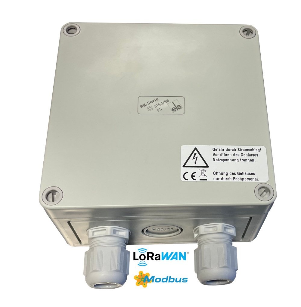
| LoRaWAN Modbus Bridge with external 230V supply and internal antenna (LOB-GW-MODBUS-LW-PWR) | |
This version has a different upload format than older versions!
If you are using 0.3.x firmware, please see the 0.3.x Manual.
If you are using 0.1.x firmware, please see the 0.1.x Manual (PDF).
If you are updating to this firmware, be aware that you will have to update your configuration and the parser in your backend.
Key Features
![]() LoRaWAN 1.0.x and 1.1 network servers supported
LoRaWAN 1.0.x and 1.1 network servers supported
![]() LoRaWAN Class A or Class C operation
LoRaWAN Class A or Class C operation
![]() LoRaWAN 1.1 time synchronisation
LoRaWAN 1.1 time synchronisation
![]() Upload capacity for up to 2.400 Modbus registers
Upload capacity for up to 2.400 Modbus registers
![]() Configuration via USB or remotely via LoRaWAN downlink
Configuration via USB or remotely via LoRaWAN downlink
![]() ModBus ASCII and RTU modes supported
ModBus ASCII and RTU modes supported
![]() Readout of ModBus Coils, Discrete Inputs, Input Registers and Holding Registers
Readout of ModBus Coils, Discrete Inputs, Input Registers and Holding Registers
![]() ModBus dialog mode via USB for easy configuration testing
ModBus dialog mode via USB for easy configuration testing
![]() Coexistence with 2nd Modbus Master possible (bus sharing, Listen before talk)
Coexistence with 2nd Modbus Master possible (bus sharing, Listen before talk)
![]() Managed Power Supply Pin can power attached Modbus Sensor
Managed Power Supply Pin can power attached Modbus Sensor
Target Measurement / Purpose
The Lobaro Modbus LoRaWAN Bridge is a low power device that can be used to communicate with Modbus Slave devices (ASCII/RTU) on a RS-485 bus over a LoRaWAN network. Modbus commands can be transmitted via Downlink message to the Bridge and are forwarded by the Bridge to the connected Slave Devices. Received responses are forwarded via LoRaWAN Uplink messages. The Modbus Bridge can also be configured to execute Modbus commands regularly and report the responses via LoRaWAN uplinks.
The Bridge supports LoRaWAN Operation Mode Class A for power efficient operation (for long operation periods powered by battery), as well as Class C to enable short reaction time to Downlink requests.

The Modbus Bridge supports reading of all four object types that can be provided by Modbus slave devices: Coil, Discrete Input, Input Register, and Holding Register. It also supports writing values to both writable objects: Coils and Holding Registers. Multiple different slave devices on the Bus can be accessed individually by a single Bridge device. Reading intervals and register definitions can be configured very flexibly to suit individual requirements.
Typical applications for Modbus devices include reading out electric and water meters or retrieving data from environmental sensors like temperature and humidity. Industrial machines as well as solar panel installations often include a Modbus connection to supply supervision and automated operation.
Supported Devices
The Lobaro Modbus LoRaWAN Bridge works with all devices that act as a Modbus Client using RTU or ASCII (Modbus TCP is not supported). Some devices that have been used successfully with the Bridge:
Device | Type | Manufacturer | More information |
|---|---|---|---|
| Octave Ultrasonic Meter | Water meter | Arad Group | External Link |
| ECL Controller | Heat/Hot Water Regulation | Danfoss | External Link |
| UMD 97 | Smart Grid Power Meter | PQ Plus | External Link (German) |
| DRS458DE | Power Meter | B+G E-Tech GmbH | External Link |
| Feuchtemessumformer PCE-P18 Modbus RTU | Humidity / Temperature sensor | PCE-Intruments | External Link (German) |
Product variants
The LoRaWAN Modbus bridge can be ordered in two standard variants. For even more customizations options see Hardware Variants overview.
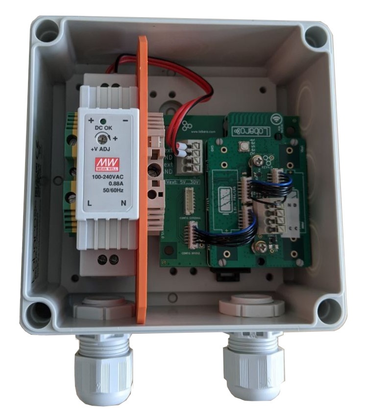
External powered std. variant (LOB-GW-MODBUS-LW-PWR)
- Modbus LoRaWAN Bridge (Ext. 230V Power, int. Antenna), Order number: 8000137
- Separately:
- LoRaWAN Modbus Bridge (ext. Power, Din-Rail, no housing), Order number: 8000043
- DR-15-5 DIN-Rail power supply 5V, Order number: 3000006
- RK 4/12-L DIN-Rail Housing, Order number: 3000005
Battery powered variant (LOB-GW-MODBUS-LW)
- LoRaWAN Modbus Bridge (XH battery connector + Ext. Power, IP67 housing), Order number: 8000041
- ER34615 (3.6V Battery, XH Connector, 0.2A), Order number: 3000169
- Request quote via E-Mail (sales@lobaro.com)
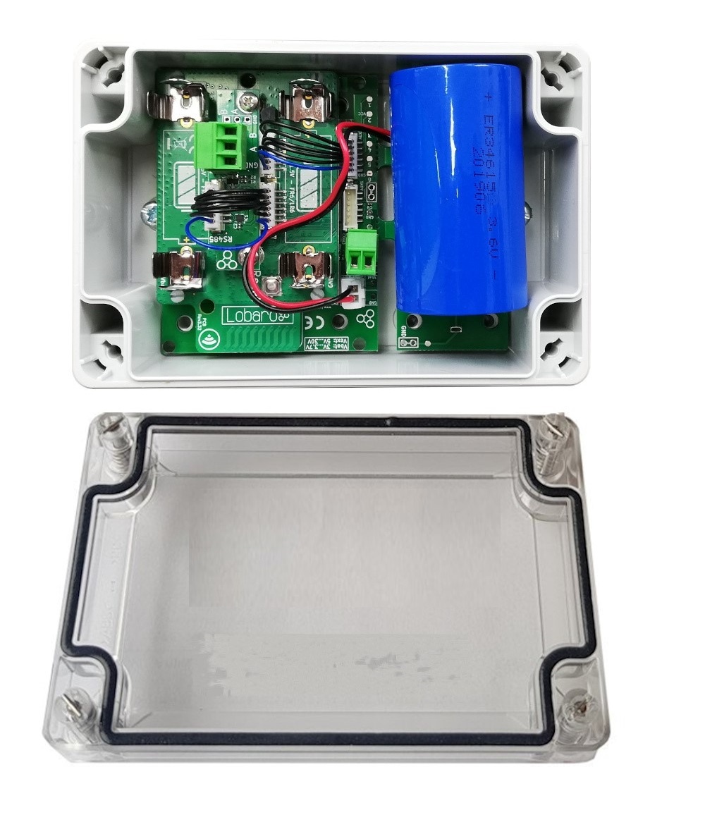
(with M8 cable gland - missing in picture)
Further customization Options
The product variants shown above are the standard variants.
Other power supply options & housing are available on request
- External antenna
- AA batteries
- NB-IoT instead of LoRaWAN
Contact us via support@lobaro.de if you need our offer for a special variant.
Modbus Introduction
For an overview about the Modbus protocol please refer to our documentation page about Modbus.
For a deeper introduction into Modbus please visit https://en.wikipedia.org/wiki/Modbus.
Quick Start Guide
Please refer to the rest of this documentation for a save and proper use of the Modbus Bridge.
This Quick Start Guide can only show you basic operations. It illustrates reading a single value from one Slave Device.
- Connect the Modbus Bridge to your Modbus Slave Device using the RS485 connection using a twisted pair cable:
AtoA,BtoB, andGNDtoGND(GNDis not strictly necessary but enhances the connection. Not all slave devices supply aGNDconnector). - Connect the Modbus Bridge to a computer using the Lobaro Configuration Adapter and the Lobaro Maintenance Tool.
- Synchronize the LoRaWAN configuration parameters between the Bridge and your Network Server.
- Make sure the Bridge is in reach of a Gateway attached to your Network Server.
- Set the Modbus Parameters according to your Slave Device (ASCII/RTU, Baud, Data Length, Stop Bits, Parity).
- Set
MbCmdto the Modbus Command to read the register you need (see below). - Save the configuration and switch to the Log tab. You should see the device requesting the data and uploading it via LoRaWAN.
MbCmd must contain the Modbus Command the Bridge will execute. The command is entered in Hex and without any check sums and is 6 bytes long (12 hexdigits). The default value is 010300000003, it consists of 4 parts: 01, 03, 0000, 0003
01
Address of the Slave Device. 1 byte: often 01 new devices
03
What kind of Modbus Register to read. 1 byte. 03 stand for Holding Register.
0000
Number/address of the first register to read. 2 bytes. Many devices have some value to read out at 0000.
0003
Number of consecutive registers to read from the first register. 2 bytes. This would read the registers #0, #1, and #2 in one command.
The format used for MbCmd is conforming to the Modbus Standard. See Configurations/Modbus Commands for a description and Examples for some more advance examples. The Modbus Bridge has a Dialog Mode that lets you try out Modbus Commands interactively which helps getting used to the syntax and helps you in trying out your slave devices.
Online Tools
Work Cycle
The Modbus LoRaWAN Bridge has a simple work cycle. It spends most of the time in a deep sleep state, to conserve energy. For every reading it wakes up for a few seconds, requests values from the connected slave devices, uploads the data via LoRaWAN, and then goes to sleep again. The following flowchart illustrates the work cycle:
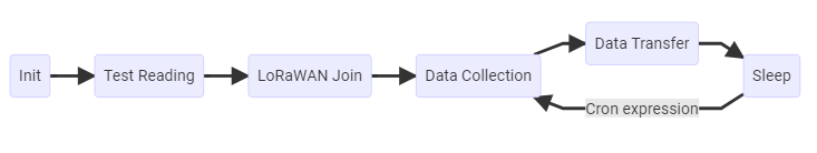
Init
When the device starts (because it has just been connected to a power source, or after a reboot) it begins in the Init state. A quick self-check is executed; if that succeeds, the green on-board LED blinks once, slowly. After that the configuration is evaluated and checked for invalid values. If any problems are detected during Init, the device's LED will light up for three times, and the device will then reboot. If everything is okay, the device will continue with the Test Reading.
Test Reading
After verifying configuration, the Bridge executes all Modbus Commands stored once without uploading the results but logging them only to the console. This makes it easy to verify all Modbus Slaves are reachable and their registers can be read. Connect your computer to the Bridge using the Lobaro Config Adapter and check the output using the Lobaro Maintenance Tool. The device will continue with LoRaWAN Join to connect to the Network (whether the test reading was successful or not does not change this).
LoRaWAN Join
The Bridge tries to connect to the LoRaWAN Network. The Details depend on the device's configuration (OTAA vs. ABP, optional Time synchronisation). Unless ABP is used, the Bridge will remain in this state until joining succeeds. It will repeat to send Join requests with decreasing frequency. After successfully attaching it enters Data Collection for the first time and starts the normal operation cycle.
Data Collection
The Bridge sends all Modbus Commands from the Configuration on the Bus and collects the answers (or lack thereof).
Data Transfer
The collected Modbus Responses are uploaded via LoRaWAN. This can take multiple upload messages depending on the amount of data collected. Once a day a status message is also uploaded, giving some information about the state of the Bridge itself. If many messages are uploaded this can take a long time. At least one message is uploaded during this state. When all data is uploaded, the device goes to Sleep.
Sleep
Between activations the device enters a very power efficient sleep mode. It stays dormant until the time specified by the Cron expression, when it changes back to Data Collection.
Configuration
The (initial) configuration is normally done using our free Lobaro Maintenance Tool and the USB PC configuration adapter.
Beside this the configuration can also be changed or read remotely in the field using LoRaWAN downlink messages, see Downlinks description.
LoRaWAN
The connection to the LoRaWAN network is defined by multiple configuration parameters. This need to be set according to your LoRaWAN network and the way your device is supposed to be attached to it, or the device will not be able to send any data.
For a detailed introduction into how this values need to be configured, please refer to the chapter LoRaWAN configuration in our LoRaWAN background article.
Name | Description | Type | Values |
|---|---|---|---|
OTAA | Activation: OTAA or ABP | bool | true= use OTAA, false= use ABP |
DevEUI | DevEUI used to identify the Device | byte[8] | e.g. 0123456789abcdef |
JoinEUI | Used for OTAA (called AppEUI in v1.0) | byte[8] | e.g. 0123456789abcdef |
AppKey | Key used for OTAA (v1.0 and v1.1) | byte[16] | |
NwkKey | Key used for OTAA (v1.1 only) | byte[16] | |
SF | Initial / maximum Spreading Factor | int | 7 - 12 |
ADR | Use Adaptive Data Rate | bool | true= use ADR, false= don't |
OpMode | Operation Mode | string | A= Class A, C= Class C |
TimeSync | Days after which to sync time | int | days, 0=don't sync time |
RndDelay | Random delay before sending | int | max seconds |
RemoteConf | Support Remote Configuration | bool | true=allow, false=deactivate |
LostReboot | Days without downlink before reboot | int | days, 0=don't reboot. See Availability Features. |
Modbus/UART
There are several values that define the configuration via Modbus. These values depend on the Slave devices that you want to read out. Please refer to your Modbus Devices's manual to find out the correct configuration.
name | description | values |
|---|---|---|
MbProt | Modbus-Protocol to use | RTU. ASCII |
MbBaud | UART Baud rate | 9600, 19200, 38400, ... |
MbDataLen | UART data length | 7, 8, 9 |
MbStopBits | UART stop bits | 0.5, 1, 1.5, 2 (written exactly like this) |
MbPar | UART parity | NONE, EVEN, ODD |
MbCron | Cron expression† defining when to read. | 0 0/15 * * * * for every 15 minutes |
MbCmd | List of Modbus Commands (see below). | 010300010003 |
PlFmt | Uplink Format | 1, 4, or 5, see Payload Formats (Formats 2 and 3 where deprecated in fw 1.3.0) |
PlMax ‡ | Message size for compact format | 10-241, dependent on Spreading Factor, see compact payload format. |
PlId ‡ | Compact format ID | 0-127, see compact payload format. |
PowerDelay ‡ | Warm up time of managed Power Supply, seconds |
|
EnDL | Enable Downlinks | true= enable sending Modbus Commands via Downlink |
DialogMode | Enable Dialog Mode | true= set the Bridge to Dialog Mode |
LbtDuration | Listen-before-talk Duration | 0= disables, 1-3600= seconds of lbt duration |
LbtSilence | Listen-before-talk Silence | 0= disabled, 1-3600 seconds of silence needed |
† See also our Introduction to Cron expressions.
‡ Since version 1.3.0.
Modbus Commands
Whenever the cron expression given in the configuration value MbCron activates, the Modbus Bridge wakes up from hibernation (or listening mode, for Class C), a set of configured Modbus Commands (set in the configuration parameter MbCmd) is executed over the RS-485 bus. Any responses received from the addressed Slave Device will be uploaded via LoRaWAN.
The Modbus Commands to be executed must be entered in the config as hexencoded bytes, exactly the way they are to be sent over the bus. Checksums must not be included in the configuration. Multiple commands can be added to the configuration, separated by commas (no spaces). For example if you want the Bridge to read the Holding Registers 100, 101, and 102 on two separated Slave Devices with the addresses 9 and 10, you would need to set MbCmd to 090300640003,0a0300640003.
You can configure any byte sequence you want to be sent; not all will be valid Modbus Commands. This feature has been developed to execute register/coil reads and upload the values retrieved. It is possible to use it for writing values as well, but the usefulness of that is limited. If you configure register writes, be aware that the commands are also executed when the device boots!
Keep in mind that the responses to your commands will be sent using LoRaWAN, which has only a very limited packet size! Modbus responses can be over 200 bytes long. For reading commands, the Modbus Response contains 6 bytes to repeat the command. The data format used by the Modbus Bridge adds another 6 bytes. On higher spreading factors with 51 byte message limit this only leaves 39 bytes for the actual read data (in EU LoRaWAN configuration, other areas might have a slightly different number). Responses that will not fit into a single LoRaWAN Uplink will be split and uploaded using multiple LoRaWAN messages. Your backend will need to those parts back together. Any message that is the continuation of an earlier uplink will be sent using port 5 (see Split Messages).
For a short introduction into Modbus Commands and some examples of configurations and their created responses, please take a look at the examples.
Listen-Before-Talk
If you want to use the Lobaro Modbus Bridge to read out values on an installation that already has an active Modbus Master, you will run into conflicts, because the Bridge acts as a Master. Normally only a single Master device is allowed on a Modbus installation. The Bridge supports a Listen-Before-Talk feature, that makes it possible to be used alongside a second Master Device (under certain conditions).
If your other Master Device has periods of non-communication that are long enough, you can configure the Bridge to wait for those pauses before starting it's own requests: When Listen-Before-Talk is activated, the Bridge does not immediately start sending on the Bus when it normally would. Instead it starts listening on the Bus until the other Master starts talking and then waits for silence to detect when the other Master just finished communicating. Only then does it send it's requests.
The Bridge waits for a maximum of LbtDuration seconds for the other Master to start communicating. Then it waits for a period of silence that lasts at least LbtSilence seconds to decide that the other master has completed its work and is now in pause.
So if, for example, your other Master has a work interval of 2 minutes and is active for about 30 seconds without longer pauses, you could set LbtDuration to 130 (10 seconds added as a buffer), and LbtSilence to 15 (make sure the value is longer than the timeout your other master has).
You will have to know exactly how your other Master acts to setup this feature.
If you set either of LbtDuration or LbtSilence to 0, you will deactivate Listen-Before-Talk completely (it is deactivated by default).
Payload formats
The Modbus Bridge sends two different kinds of messages over three different LoRaWAN ports:
Direction | Port | PlFmt Value | Message |
|---|---|---|---|
| Uplink | 1 | any | Status messages. |
| Uplink | 3 | 1 | Modbus Responses triggered by configuration. |
| Uplink | 4 | any | Modbus Responses triggered by Downlinks. |
| Uplink | 5 | any | Continuation of Responses that do not fit in a single Uplink. |
| Uplink | 6 | 2 | Compact payload format with timestamp |
| Uplink | 7 | 3 | Compact payload format without timestamp |
| Uplink | 128 | any | Remote configuration response |
| Uplink | 129-131 | any | Remote configuration long response 129 = start, 130 = middle, 131 = last |
| Downlink | 4 | any | Modbus Commands to be forwarded by the Bridge. |
| Downlink | 128 | any | Remote configuration |
In addition to the description we also supply a reference decoder usable in TTN at the end of this document.
Uplink Messages
Status message (Port 1)
The Modbus Bridge sends a status messages report on the health of the device itself. This messages are sent along when the device is sending data packages with a maximum of one status message per day.
Status messages are transmitted on port 1 and have a fixed length of 16 bytes.
name | pos | len | type | description | example |
|---|---|---|---|---|---|
| version | 0 | 3 | uint8[3] | Version of firmware running on the device | [0, 4, 1] ≡ v0.4.1 |
| flag | 3 | 1 | uint8 | Status flag, for internal use | 0 |
| temperature | 4 | 2 | int16 | Device's internal temperature in tenth °C | 246 ≡ 24.6°C |
| voltage | 6 | 2 | uint16 | Voltage supplied by power source in mV | 3547 ≡ 3.547V |
| timestamp | 8 | 5 | int40 | Internal date/time at creation of the status packet as UNIX timestamp | 1533055905 |
| plFmt | 13 | 1 | uint8 | The configured payload format | 1, 2, 3, 4, 5 |
| resetReason‡ | 14 | 1 | uint8 | Cause of latest reset, coded | 0 |
| finalWords‡ | 15 | 1 | uint8 | Last info before latest reset, coded | 0 |
‡ Since version 1.3.0.
Reset Reason Code
The reset reason reports what triggered the latest reboot (which might have happend month ago). The information is coded in a single unsigned byte:
| Hex | Dec | Name | Meaning |
|---|---|---|---|
0x01 | 1 | LOW_POWER_RESET | Supply voltage dropped critically. Low battery? |
0x02 | 2 | WINDOW_WATCHDOG_RESET | |
0x03 | 3 | INDEPENDENT_WATCHDOG_RESET | |
0x04 | 4 | SOFTWARE_RESET | Reboot triggered by Firmware, check final words |
0x05 | 5 | POWER_ON_RESET | Power turned on, e.g. battery inserted, connected to grid |
0x06 | 6 | EXTERNAL_RESET_PIN_RESET | Reset button pressed or reset via config adapter |
0x07 | 7 |
| |
0xff | 255 |
|
Final words
When the device reboots actively, it saves the information what triggered the reboot. Some of these codes (below 0x10) are only useful for debugging the firmware by Lobaro. See Availability Features for more information. The Final Words are coded in a single unsigned byte:
| Hex | Dec | Name | Meaning |
|---|---|---|---|
0x00 | 0 | NONE | No information available / externally triggered reset (check reset reason). |
0x01 | 1 | RESET | Intentional reset by firmware without additional information. |
0x02 | 2 | ASSERT | Assertion error in firmware. |
0x03 | 3 | STACK_OVERFLOW | Stack overflow error in firmware. |
0x04 | 4 | HARD_FAULT | Assertion error in firmware. |
0x05 | 5 | OUT_OF_MEMORY | Firmware failed to allocate a critical portion of memory. |
0x10 | 16 | INVALID_CONFIG | Invalid configuration was detected (might have triggered config revert after remote config). |
0x11 | 17 | REMOTE_RESET | Remote command (via downlink config) caused reboot. |
0x12 | 18 | NETWORK_LOST | Device detected loss of LoRaWAN network and decided to rejoin (see LostReboot config parameter). |
0x13 | 19 | NETWORK_FAIL | Device failed to join LoRaWAN network after parameter where changed via remote config. |
Data messages - verbose format (Port 3, PlFmt=1)
Data messages contain responses to Modbus Commands received by the Bridge. The Bridge supports multiple Payload formats for different use cases. The format is selected by the configuration parameter PlFmt:
1: Verbose payload format (port 3)
The verbose payload format (PlFmt=1) is the standard setting of the Bridge. It is designed to be very versatile (it uploads the complete Response sent by the Slave Devices, so reading registers as well as writing registers are both supported). It contains all information you need to know the register and the slave device your data is coming from. You do not need to know the exact configuration of your devices in your backend to be able to parse the data. This is convenient when you have man Modbus Bridges with different configuration in the field. This payload format is also good in communicating error conditions in case the executed Modbus Commands fail. The trade off is overhead in the transmission. If you need to get a lot of data uploaded often, this could be a problem for you with the limited LoRaWAN bandwidth. If this is a problem for your use case, you should take a look at the compact data formats.
Data messages using the verbose payload format are uploaded on port 3. Every message starts with a 5 byte timestamp (UNIX timestamp as big endian int40, see timestamps in our LoRaWAN devices) for more information). The timestamp is followed by one or more responses of varying length.
Each of the responses starts with a single byte (uint8) indicating the length of its payload (len) followed by that many bytes of payload. The payload consists of the raw Modbus response as sent by the Slave Device followed by 3 additional bytes: the first register/coil as uint16 (big endian) and the number of registers/coils as uint8 taken from the executed command. The following tables visualise the message structure. See the Examples Section for some sample data messages explained down to the individual bytes. We also provide a Reference Decoder in JavaScript that can read the format.
The timestamp in the message is the wakeup time when the device was activated by the cron expression in MbCron (using the devices internal clock), so all Uplinks from a single activation will have the same Timestamp. The Modbus Response in the message in addition with the start register/coil and the register/coil count makes it possible to know which registers/coils where exactly read/written, what kind they were, and the address of the device. For Modbus Commands that do not have a register/coil count (like function 5, forcing a single coil), or for those that do not contain a start register/coil (e.g. funtion 7, reading exception status), the contents of the additional fields start register and/or count are undefined. The payload format used only a single byte for the count value, so if you are reading/writing more than 255 coils, the higher byte will be cut off.
The Bridge puts as many responses as in one message as possible (without changing the order of responses and respecting the maximal message size of the current Spreading Factor). If the responses do not fit into a single message it will upload as many messages as needed. When a single response is too long to fit in a message, the response will be split up over multiple messages and will need to be reassembled in the backend. See Split Messages for instructions on how to do that and how to prevent splitting.
Structure of a message on port 3:
Bytes  | 0 . 1 . 2 . 3 . 4 | 5 ...      | ...        | ... | ...        |
       +-------------------+------------+------------+-----+------------+
Part   | timestamp         | response 1 | response 2 | ... | response n |
Structure of a response part on port 3:
Bytes  | 0   | 1 .. len-3      | len-2 . len-1  | len   |
       +-----+-----------------+----------------+-------+
Field  | len | Modbus response | start register | count |
Response to Downlink (Port 4)
A Downlink Modbus Command can be executed on Downlink Port 4. The answer has the verbose payload format like described above on port 3.
The Timestamp in Port 4 Uplinks is the time when the Downlink containing the Command was received (according to the devices internal clock).
For details about the downlink see below.
Split messages (Port 5)
If a single Modbus Response does not fit into a LoRaWAN uplink, due to the length restriction for the current Spreading Factor, the message is split up into multiple Uplinks. The first part will be sent on Port 3 (for cron triggered reads) or on Port 4 (for reads triggered by downlink). The remaining Bytes will be sent in the following uplinks on Port 5 in as many Uplinks as needed. You can know that an Uplink is split, when the length information (Byte 0 in the response part) is longer than the data following it. The payload from Port 5 must be appended to the last uplink received on either Port 3 or 4 in your application server, before you can parse the message. Check the frame counter to make sure you receive all parts. For very long responses and high Spreading Factors, splits over up to 6 messages are possible.
Split messages will only ever contain a single Modbus Response. If multiple Responses are transmitted, they will be put in separat Port 3 or Port 4 Uplinks.
You can prevent splitting of messages completly, if you make sure your Responses will never be longer than 42 Bytes (or longer if you reduce the Spreading Factor). You can also change to using the Compact Payload Format to avoid Splitting.
The Examples section contains an illustration of a split up Response.
Deprecated Format (Port 6/7, PlFmt=2/3)
Prior to Firmware Version 1.3.0 there was a different Compact Payload Format on Ports 6-7. That format was never completly documented and had issues with long payloads. It has therefore been deprecated in v1.3.0 and been replaced by the new Compact Payload Format (Ports 20-59). If you have setups that use this format, please migrate them to the new format, of continue to use the Firmware v1.2.2.
Compact Payload Format (Port 20-59, PlFmt=4&5)
The Modbus Bridge provides an alternative Payload Format for uplinks that uses the limited bandwidth more efficiently by only sending data. This requires a dedicated parser on the network server of application server that has knowledge of the device's configuration. The configuration can be requested from devices in the field with our Remote Configuration. Be aware that Error Conditions cannot be communicated as well in this format.
If you have problems writing a dedicated parser, please contact Lobaro, we can provide you with an offer for writing it for you.
When using the compact format, all Modbus Command from MbCmd is executed in order. Only the payload is taken from the responses, as it is sent by the Modbus Slaves. As many responses as fit in a single upload are connectated and send on Port 20. The next responses connectated are send on Port 21 and so forth, up to port 59 (so there can be up to 40 different uplinks). The Uplinks are prefixed with a short Message Header. When a Modbus Command fails to execute, an Error Indicator is set and the Bytes for that command are set to 0xff.
On booting, the device prints the complete Payload Format in the Log, so it is relatively easy to write a parser with that information (only for Payload Formats 4 and 5).
There are 4 ConfigParameters that influence the format: PlFmt, PlMax, PlId, and of course MbCmd.
PlFmt=5 sends a Message Header of 1 byte, containing an error indicator (highest bit) and the value given in PlId (lowest 7 bits).PlFmt=4 sends a Message Header of 6 byte, consiting of the same byte as in PlFmt=5 followed by a 5 Byte timestamp (int40 BE Unix Timestamp).
PlId is a numeric value 0-127 that is simply uploaded with each Uplink. This can be used for advanced setups where you have multiple different configurations for a big number of devices, so that the parser knows, what configuration to use.
PlMax limits the number of Bytes that will be used per Uplink (including the Message Header of 1 or 6 bytes). This an advanced parameter that can be used to optimise distribution of data over the Uplink messages. This value is limited by the LoRaWAN restrictions and cannot be set higher than possible for the configurated Spreading Factor (ConfigParameter SF). For the default SF of 12 it is limited to 51 Bytes. See Spreading Factor in our LoRaWAN background article for all numbers. Be aware, that selecting a lower Spreading Factor will decrease the range your device can communicate via LoRaWAN drastically. No single ModbusCommand must create a Payload that does not fit into this limit (after also including the Message Header).
The Timestamp contains the time the device wakes up by the cron (according to the internal clock). So all Uplinks from the same activation will have the same Timestamp and are easy to associate.
Remote Config (Port 128-131)
When Remote Configuration is enabled, you can send Downlinks on Port 128 to read or set Config Parameters and execute commands like Reboot. Responses to those Downlinks are set on port 128 (or 129-131 if they are too long for a single Uplink).
Downlink
Please be aware that Downlinks in LoRaWAN can only be received when the device sends an Uplink, or when the device operates in Class C mode. See Uplinks and Downlinks in our LoRaWAN page for more information. Also, reception quality of Downlinks is typically worse than reception quality of Uplinks.
Modbus Commands (Port 4)
Downlinks on port 4 contain one or more Modbus Commands that the Bridge should forward to the RS-485 bus. Every Command must be prefixed by a single byte defining the Command's length as uint8. The Modbus Commands must be sent as raw bytes and without any check digits.
The Responses to the Commands are sent as Uplink messages on port 4. The payload format on port 4 is the same as on port 3 (see Data messages), only that the timestamp indicates the time the downlink was received by the Bridge.
Any byte sequence can transmitted this way and will be forwarded to the bus. If the Bridge does not receive a Response by the addressed Slave Device, it creates an error Response with the exception code 11 "Gateway Target Device Failed to Respond". This only makes sense if the Downlink did contain a Modbus Command, but it will be performed for any sequence of bytes you send. Commands must have a length of at least 3 bytes.
Please be advised that not all Modbus Slave devices send Responses in all cases. If you receive the exception code 11 it is possible that the Slave device was reached but was not addressed correctly. It might even be possible, that a Command was executed successfully, but that the device does not send confirmations. When in doubt, refer to the documentation of your connected devices or try communicating with it directly from your computer or using the Dialog Mode, to reduce possible error sources.
Refer to Examples to see some Downlinks and their answers.
Remote Configuration (Port 128)
The Modbus Bridge supports configuration via LoRaWAN Downlinks. It receives commands on port 128.
See Remote Configuration in our LoRaWAN page for instructions on how to use it.
Supported downlink messages:
| Char | Command | Parameter | Hex | Version required |
|---|---|---|---|---|
? | Request firmware and version | None | 3F | |
g | Get config parameter value | <name> | 67 | |
r | Reset config parameter value | <name> | 72 | |
s | Set config parameter value | <name>=<value> | 73 | |
| S | Set config parameter value + Save and reboot | <name>=<value> | 53 | 1.3.0 |
a | Append to config parameter value | <name>=<value> | 61 | |
b | Reboot device without saving | None | 62 | |
w | Save config and reboot device | None | 77 |
<name> is the ASCII encoded name of the parameter
- <value> is the ASCII encoded value
LED Patterns
The Modbus Bridge contains a green LED that is used to give feedback of it's operations. 5 short flashes in sequence indicate some kind of failure
| Pattern | Pattern description | Meaning |
|---|---|---|
| — | 0.5s on | Device just booted |
-- · | Two long, one short | Successful Modbus readout (all commands) |
-- ····· | Two long, five short | Modbus readout failed (at least one command) |
--- · | Three long, one short | OTTA Join successfull |
--- ····· | Three long, five short | OTTA Join failed (will retry with exponential timeout up to 8h) |
Feedback on boot
On boot (e.g. after pressing reset button), the Bridge flashes for half a second: —
After that it does a test Modbus readout of all configured commands. If all succeed, it will flash -- ·, if one or more commands fail (because of error in the connection or because of misconfiguration, e.g. invalid registers), it will flash -- ····· instead.
If the device is configured for OTAA Join, it will then try to join the LoRaWAN Network. On success it will flash --- · If the OTAA Join fails, it will flash --- ····· and then retry to join until it succeeds (with exponentially growing timeouts, starting at 30s and maxing out at 8h).
This Feedback allows to quickly check an installed device to work correctly without the need to attach a PC, by simply pressing the reset-button.
Sensor Power Supply
The Modbus Bridge has the ability to supply a connected sensor with power (within limits). The connector pins include a GND and a VCC pin that can be used to power an external device, e.g. an attached sensor that will be read out over Modbus. With the battery powered version of the Modbus Bridge this can be used to build autonomous radio connected sensors with low power Modbus capable sensors. VCC is 3.3VDC (230V variant) or the 3.6V battery voltage (battery powered variant).
Older hardware revisions do not include the VCC pin. Those revisions cannot be used to power an external sensor.
Managed VCC
The VCC pin on the Modbus connector is managed by the Bridge (meaning, that it can be turned on and off as needed). The power is activated while the Bridge sends commands via Modbus and is deactivated when communication has completed.
Sensors might need time to be ready for read out on power on, so it is possible to add a delay between power on and communication. The ConfigParameter PowerDelay can be set to a time in seconds that should be waited (0s up to 1h).
The special value -1 can be used for PowerDelay to have the power turned on permanently, if you want to attach a device that needs continuous power.
Voltage and Current
When VCC is active, it is connected to the voltage regulator (3.3V, 0.5A max for the externally powered version), or directly to the battery (3.6V, 0.2A max for the battery version). The Modbus Bridge itself draws up to ~0.1A on uploads, but only ~0.01A during Modbus readouts (when the managed VCC is normally active).
Availability Features
The Device has availability as a high priority. It implements features that try to avoid it ever beeing out in the field impossible to be reached. This can lead to reboots and config resets that are difficult to understand without additional background.
Daily Status Message
Independent of the measure cron given in the configuration, the device wakes up at least once a day to send a status message. This gives the user a chance to change the devices configuration (via downlinks), even it is set to only send one uplink per year (either intentionally or by accident). It will also let you know if there is a problem with the device (low battery, vandalisation) before your important yearly readout failes to be executed.
Lost Network Detection
In LoRaWAN there exists a session between the Device and the Network Server. This is typically created on OTAA Join. This session can be lost on side of the Network Server (Database problems, etc). If this happens, the only way to establish connection with the Device again is by rebooting it. With the session lost this normally means you need physical access to the device to trigger a reset.
Out LoRaWAN Devices have a feature that detects a lost connection to the LoRaWAN Network within days and triggers a reboot to trigger a new OTAA Join. It is controlled by the ConfigParameter LostReboot. You can indicate a number of days there. If the Device does not receive any Downlinks for that number of days, it decides the Network has been lost and it reboots. Any Downlink received counts for this feature: ADR, time synchronisation, ACKs, remote config. After half of the configured time has been passed without a Downlink, the Device starts to request ACKs from the Network to enforce a Downlink message.
When this feature triggers a reboot, it will be reported in the Final Words of the Status Message as NETWORK_LOST = 0x12.
The time span for this feature is relatively long on purpose (10 days default), because it is meant to catch edge cases only and we do not want false positives to trigger unnecessary reboots.
Setting LostReboot to 0 deactivates this feature completely.
This feature can also be used if you decide to switch your LoRaWAN Network, e.g. if you start your role out with public TTN and later decide to switch to your own network solution. Simply create the devices in your new Network Server and delete them in the old. After the number of day passes, the devices will reboot and join the new network (alternatively you can use remote config for that to avoid the donwtime).
OTAA retries
When the Device fails its OTAA Join with the Network, it will retry indefinitely until it succeeds. The first retry will happen after 30s. With each failure it will double the timeout between attempts until a maximal time of 8h has been reached. This is a tradeof between waiting time and battery life, in case there is a long lasting Network problem. The timeouts will have an additional random delay added, so that multiple Devices in close proximity will not all send at the same time.
Remote Configuration Confirmation
It is easy to set the Device to an invalid configuration. For remote configuration a changed configuration will therefore be marked as temporary until it has been tried and confirmed to work (unless you use the override feature, which you should not do outside of very special cases). When the new configuration fails, the previous one is restored and the device rebooted. This will be reported in the Final Words of the Status Message as INVALID_CONFIG = 0x10.
If you change the LoRaWAN parameters for OTAA via remote config, the Device will try up to 5 times to do the OTAA Join. If that fails, the config will be reverted. This will be reported in the Final Words of the Status Message as NETWORK_FAIL = 0x13.
Examples
This chapter illustrates with some examples, how working with the Modbus Bridge looks like. The bytes that are sent via LoRaWAN are presented here as hex strings, while on the air they are sent as raw bytes. Modbus Commands and Responses are broken down to their parts in the explanations, but explaining the format used by Modbus in detail is beyond the scope of this manual. You can find a short explanation on Modbus on Wikipedia: https://en.wikipedia.org/wiki/Modbus.
Uplinks in Verbose Payload Format (PlFmt=1)
The following shows some examples of configuration for the automated reading and what the generated Uplinks for that could look like.
Example A1: Read Holding Registers 0, 1, and 2 of device with address 1
MbCmd = '010300000003'

# Example resulting Uplink after successful readout
Up, Port 3: '005d1698fd0c0103061234567890ab000003'
 '005d1698fd' -> timestamp = 1561762045 -> 2019-06-28T22:47:25 UTC
 '0c'       -> first Response is 12 bytes long
 '0103061234567890ab000003' 12 bytes modbus response:
   '01' -> slave device with address 1
   '03' -> function 3 = read Holding Register, success
   '06' -> 6 bytes of data in Response following
   '1234567890ab' -> 6 bytes of data
   '0000' -> start reading at register 0
   '03' -> read 3 consecutive registers

# Example resulting Uplink after failing readout
Up, Port 3: '005d1698fd0601830b000003'
 '005d1698fd' -> timestamp = 1561762045 -> 2019-06-28T22:47:25 UTC
 '06'       -> first Response is 6 bytes long
 '01830b000003' 3 bytes modbus response:
   '01' -> slave device with address 1
   '83' -> function 3 with error indicator 80 = read Holding Register, failed
   '0b' -> error code 11: "Gateway Target Device Failed to Respond"
   '0000' -> start reading at register 0
   '03' -> read 3 consecutive registers
Example A2: Read coils 1000-1019 of device 32
MbCmd = '200103e80014'
# Example resulting Uplink

Up, Port 3: '005d1698fd 09 200103f1041a03e814'

 '005d1698fd' -> timestamp = 1561762045 -> 2019-06-28T22:47:25 UTC

 '09'       -> first Response is 9 bytes long

 '200103f1041a03e814' 9 bytes of response:

  '20' -> slave device with address 32

  '01' -> read coils, success

  '03' -> 3 bytes of data

  'f1041a' -> 20 bits of data packed into 3 bytes

  '03e8' -> start reading at coil 1000

  '14' -> read 20 consecutive coils
Example A3: Read registers from two devices
MbCmd = '0a0300010005,3001ea600020'
# Example resulting Uplink

Up, Port 3: '005d1698fd100a030a111122223333444455550001050a30010412345678ea6020'

 '005d1698fd' -> timestamp = 1561762045 -> 2019-06-28T22:47:25 UTC

 '10' -> first Response is 16 bytes long

 '0a030a11112222333344445555000105' 16 bytes of Response

  '0a' -> slave device with address 10

  '03' -> read Holding Registers, success

  '0a' -> 10 bytes of data following

  '11112222333344445555' 10 bytes of data

  '0001' -> start reading at register 1

  '05' -> read 5 registers

 '0a' -> second Response is 10 bytes long

 '30010412345678ea6020' 10 bytes of Response

  '30' -> slave device with address 48

  '01' -> read Coils, success

  '04' -> 4 bytes of data following

  '12345678' -> 32 bits of data packed in 4 bytes

  'ea60' -> start at coil 60000

  '20' -> read 32 coils
Example A4: Split uplink message
MbCmd = '010300010020'

# Command reads 32 consecutive registers resulting in 64 bytes payload
# Example resulting Uplinks for a Spreading Factor of 12 with 51 bytes of payload per message

Up 1, Port 3: '005d1698fd46010340000100020003000400050006000700080009000a000b000c000d000e000f001000110012001300140015'

  '005d1698fd' -> timestamp = 1561762045 -> 2019-06-28T22:47:25 UTC

  '46' -> first Response is 70 bytes long
  since the remainder of the message does not contain 70 bytes,
  you know there must be an additional part coming

Up 2, Port 5: '0016001700180019001a001b001c001d001e001f00200120'

  This contains the rest of the message. Appended to the previous message, it adds up to the correct number of bytes.
Uplinks triggered by Downlink Commands
Example B1: Read single Input Register by Downlink
Down, Port 4: '06180401000001'

 '06' -> first Command is 6 bytes long

 '180401000001' 6 bytes of Modbus Command

  '18' -> slave device with address 24

  '04' -> function 4, read Input Register

  '0100' -> start at register 256
    '0001' -> read 1 register
# Example resulting Uplink

Up, Port4: '004b3dd67508180402abcd010001'

 '004b3dd675' -> timestamp = 1262343797 -> 2010-01-01T11:03:17 UTC

 '08' -> first Response is 8 bytes long

 '180404abcd010001' 8 bytes of Response

  '18' -> slave device with address 24

  '04' -> read Input Register, success

  '02' -> 2 bytes of data following

  'abcd' -> 2 bytes of data

  '0100' -> start at register 256

  '01' -> read 1 register
Example B2: Writing holding registers on multiple devices
Down, Port 4: '06a106aabb12340fa210a0010004081122334455667788'

 '06' -> first Command is 6 bytes long

 'a106aabb1234' 6 bytes of Modbus Command

  'a1' -> slave device with address 161

  '06' -> function 6, write single Holding Register

  'aabb' -> address of Register to write = 43707

  '1234' -> two bytes of data

 '0f' -> second Command is 15 bytes long

 'a210a0010004081122334455667788' 15 byte of Modbus Command

  'a2' -> slave device with address 162

  '10' -> function 16, write multiple Holding Registers

  'a001' -> start at register 40961

  '0004' -> 4 registers to write

  '08' -> 8 bytes of data follow

  '1122334455667788' -> 8 bytes of data
# Example resulting Uplink
Up, Port 4: '004b3dd67506a1860200000006a210a0010004'

 '004b3dd675' -> timestamp = 1262343797 -> 2010-01-01T11:03:17 UTC

 '06' -> first Response is 3 bytes long

 'a18602000000' 3 bytes of Modbus Response

  'a1' -> slave device address 161
    '86' -> write single Holding Regsiter, failed

  '02' -> error code 2: "Illegal Data Address"

  '0000' -> start register not used (undefined)

  '00' -> count not used (undefined)

 '06' - second Response is 6 bytes long

 'a210a0010004' 6 bytes of Modbus Response

  'a2' -> slave device address 162

  '10' -> write multiple Holding Registers, success

  'a001' -> start at register 40961

  '0004' -> 4 registers to write
Uplinks in Compact Payload Format
Example C1: Single Modbus Command, PlFmt 4
# Attached device: B+G E-Tech power Meter

# Config:
MbCmd = 010300000003  -> Read registers 0 to 3 from Slave 1
PlFmt = 4             -> Compact Format with Timestamp
PlMax = 51            -> Max 51 Bytes per Uplink
PlId  = 0             -> Payload Id = 0

# Info from Log
APP| Number of commands to be executed on cron: 1
APP|   01 03 00 00 00 03
APP| Compact format definition, id=0, max size=51
APP|   Port 20:
APP|     000-000=error&fmt-id
APP|     001-005=timestamp
APP|     006-011=resp(010300000003)

# Successful readout, leading to Uplink on Port 20: '00005fd8bf08000000010033'
  '00' -> '0' no error, '00' -> PlId = 0
  '005fd8bf08' -> timestamp = 1608040200 -> 2020-12-15T13:50:00 UTC
  '000000010033' -> 6 Bytes data from 3 Registers -> 3.07 kWh

# Failed readout, leading to Uplink on Port 20: '80005fd8c7caffffffffffff'
  '80' -> '1' error in any of the responses, '00' -> PlId = 0
  '005fd8c7ca' -> timestamp = 1608042442 -> 2020-12-15T14:27:22 UTC
  'ffffffffffff' -> 6 Bytes set to 0xff, indicating error
Example C2: Multiple Commands, PlFmt 5
# Attached devices: Multiple B+G E-Tech power Meters

# Config:
MbCmd = 010300000003,020300000003 -> Read registers 0 to 3 from Slave 1
PlFmt = 5                         -> Compact Format with Timestamp
PlMax = 51                        -> Max 51 Bytes per Uplink
PlId  = 13                        -> Payload Id = 13

# Info from Log
APP| Number of commands to be executed on cron: 2
APP|   01 03 00 00 00 03
APP|   02 03 00 00 00 03
APP| Compact format definition, id=29, max size=51
APP|   Port 20:
APP|     000-000=error&fmt-id
APP|     001-006=resp(010300000003)
APP|     007-012=resp(020300000003)

# Successful readout of both, leading to Uplink on Port 20: '1d0000000100330000001a0040'
  '1d' -> '0' no error, '1d' -> PlId = 13
  '000000010033' -> 6 Bytes data from 3 Registers, Meter 1 ->  3.07 kWh
  '0000001a0040' -> 6 Bytes data from 3 Registers, Meter 2 -> 67.20 kWh

# Partly successful readout, leading to Uplink on Port 20: '9d000000010033ffffffffffff'
  '9d' -> '1' error (in any of the values in message), '1d' -> PlId = 13
  '000000010033' -> 6 Bytes data from 3 Registers, Meter 1 -> 3.07 kWh
  'ffffffffffff' -> 6 Bytes set to 0xff to indicate error, Meter 2

# Failed readout, leading to Uplink on Port 20: '9dffffffffffffffffffffffff'
  '9d' -> '1' error (in any of the values in message), '1d' -> PlId = 13
  'ffffffffffff' -> 6 Bytes set to 0xff to indicate error, Meter 1
  'ffffffffffff' -> 6 Bytes set to 0xff to indicate error, Meter 2
Example C3: Multimple Commands, leading in multiple Upoads, PlFmt 5
# Config
MbCmd = 010300000010,010301000004,0103020a000c,010300800008
PlFmt = 5                         -> Compact Format with Timestamp
PlMax = 40                        -> Max 40 Bytes per Uplink
PlId  = 10                        -> Payload Id = 10

# Info from Log
APP| Number of commands to be executed on cron: 4
APP|   01 03 00 00 00 10
APP|   01 03 01 00 00 04
APP|   01 03 02 0A 00 0C
APP|   01 03 00 80 00 08
APP| Compact format definition, id=10, max size=40
APP|   Port 20:
APP|     000-000=error&fmt-id
APP|     001-032=resp(010300000010)
APP|   Port 21:
APP|     000-000=error&fmt-id
APP|     001-008=resp(010301000004)
APP|     009-032=resp(0103020a000c)
APP|   Port 22:
APP|     000-000=error&fmt-id
APP|     001-016=resp(010300800008)

# Resulting in 3 consecutive uploads on Port 20-22:
# Port 20: 0a0000000100020003000400050006000700080009000a000b000c000d000e000f
  '0a' -> '0' no error, '0a' -> PlId 10
  '0000000100020003000400050006000700080009000a000b000c000d000e000f' -> 32 Bytes of Data from Registers 0x0000-0x000f
# Port 21: 8affffffffffffffff111122223333444455556666777788889999aaaabbbbcccc
  '8a' -> '1' error occured, '0a' -> PlId 10
  'ffffffffffffffff' -> 8 Bytes set to 0xff indicating error reading Registers 0x0100-0x0103
  '111122223333444455556666777788889999aaaabbbbcccc' -> 24 Bytes of Data from Registers 0x020a-0x0215
# Port 22: 0a01010202030304040505060607070808
  '0a' -> '0' no error, '0a' -> PlId 10
  '01010202030304040505060607070808' -> 16 Bytes of Data from Registers 0x0080-0x0087
Dialog Mode
The Modbus Bridge has an additional interactive Operation Mode that can help finding the correct Modbus Commands for normal operations. You enter it by setting the Configuration Parameter DialogMode to true using the Lobaro Configuration Adapter and the Lobaro Maintenance Tool. After saving the configuration the device will reboot and enter Dialog Mode. To change the device back to normal operations change the Parameter DialogMode back to false and save the config.
In Dialog Mode the Bridge will not connect to the LoRaWAN Network and it will not execute any operations on its own. It will wait for user input over the Lobaro Maintenance Tool. On the tab showing the device's log messages there is an input field labeled Send via UART. You can enter Modbus commands here, followed by pressing return. The Bridge will send the commands over the bus just as it would if it got them from configuration. The response will be observable in the Log.
The Commands must be entered as hex strings without any check sums. The Modbus parameters (UART configuration and Modbus Mode RTU/ASCII) are taken from the configuration just as during normal operations. The Bridge operates as an interactive Modbus master device that can be used for diagnosing Modbus installations or executing a few commands on a device that has no permanent Modbus connection.
In Dialog Mode the device does not enter any sleep states.
If you leave the Modbus Bridge in DialogMode while it is powered by battery it will quickly drain the battery and run out of power. It is not possible to enter the DialogMode via RemoteConfig.
Dialog Mode Example
Command sent via UART:

'010300100002'

  Read Holding Registers #16 and #17 from slave device with address 1.
Possible Responses:

'01830b' ->

  Device did not respond or could not be reached
    (error code 11, generated by Bridge)
'018302' ->
  Reading holding registers with that addresses not supported by device
    (error code 2, generated by Slave device with address 1)
'010300100002abcd1234' ->

  Successful readout of registers:
    register #16: 'abcd'
    register #17: '1234'
Complex setups
The Modbus Bridge as described in this manual can be individually configured to read out any registers and coils. For some setups, this is not enough. There can be situations in which you want to read registers at different intervals, e.g. you might need some values with hourly updates and others only every other day. For measuring values with high variance it can be necessary to take multiple reads over a period of time and create an average value. Maybe you need to read a status register first and depending on its value you want to decide which registers to read and transmit the values of. All this scenarios are possible to solve using the Modbus Bridge, but their complexity leave the scope of our standard firmware. If you need any special processing for your Modbus setup, please contact us with your requirements, and we will make you an offer for an individual firmware that processes data the way you need. If you find that the data rate LoRaWAN offers is a limitation for your setup, we could also provide you with a Modbus solution that uses alternate data transmission technologies, for example NarrowBand-IoT.
Appendices
Technical characteristics
| Product | |
| Type name (230V) | LOB-GW-MODBUS-LW-PWR |
| Type name (3.6V Battery) | LOB-GW-MODBUS-LW |
| Description | Modbus Bridge (LoRaWAN) (Ext. 230V Power, Int. Antenna) |
| RF tranceiver | |
| Type | Semtech SX1272 |
| Frequency | 863 MHz to 870 MHz |
| Max. TX Power | max. +13 dBm |
| Typical RF Range | ≤2km |
| Ideal RF Range | ≤10km (free line of sight) |
| LoRa communication | |
| Protocol | Class A / Class C LoRaWAN 1.0.2 EU868 Experimental: LoRaWAN 1.1 |
| Activation method | Over-the-air-activation (OTAA) Activation by personalization (ABP) |
| Encryption | AES128 |
| Modbus communication | |
| Bus | RS-485 twisted pair wires (with optional GND) |
| Protocol | RTU/ASCII |
| Bus IO Protection | >±15 kV HBM Protection |
| Bus IO Protection | >±12 kV IEC 61000-4-2 Contact Discharge |
| Bus IO Protection | >±4 kV IEC 61000-4-4 Fast Transient Burst |
| Max. RS485 Cable Length | 3m (longer cables possible but not tested) |
| Environmental Requirements | |
| Operating temperature | -20°C – 55°C |
| Max installation height | 2m |
Standards | |


CE Declaration of Conformity
CE Declaration DR-15-5 Power Supply (pdf).
Disposal / WEEE / Entsorgung
Information about the disposal of the Device.
Reference decoder
This is a decoder written in JavaScript that can be used to parse the device's LoRaWAN messages. It can be used as is in The Things Network.
function readVersion(bytes) {
    if (bytes.length<3) {
        return null;
    }
    return "v" + bytes[0] + "." + bytes[1] + "." + bytes[2];
}

function int40_BE(bytes, idx) {
    bytes = bytes.slice(idx || 0);
    return bytes[0] << 32 |
        bytes[1] << 24 | bytes[2] << 16 | bytes[3] << 8 | bytes[4] << 0;
}

function int16_BE(bytes, idx) {
    bytes = bytes.slice(idx || 0);
    return bytes[0] << 8 | bytes[1] << 0;
}

function uint16_BE(bytes, idx) {
    bytes = bytes.slice(idx || 0);
    return bytes[0] << 8 | bytes[1] << 0;
}

function port1(bytes) {
    return {
        "port":1,
        "version":readVersion(bytes),
        "flags":bytes[3],
        "temp": int16_BE(bytes, 4) / 10,
        "vBat": int16_BE(bytes, 6) / 1000,
        "timestamp": int40_BE(bytes, 8),
        "operationMode": bytes[13],
        "noData": !!(bytes[3] & 0x01)
    };
}

function port2(bytes) {
    var regs = [];
    if (bytes.length > 5) {
        // loop through data packs
        var b = bytes.slice(5);
        while (b.length>=4) {
            var r = {
                "device":b[0],
                "register":int16_BE(b, 1),
                "count":b[3] & 0x3f,
                "error":!!(b[3]>>7),
                "data":null
            };
            var dataLen = r["count"]*2;
            if (b.length >= dataLen+4) {
                r["data"] = b.slice(4, 4 + dataLen);
            }
            regs.push(r);
            b = b.slice(4+dataLen);
        }
    }
    return {
        "port":2,
        "timestamp": int40_BE(bytes, 0),
        "registers": regs
    };
}

function modbusErrorString(code) {
    // Modbus exception codes
    // see https://en.wikipedia.org/wiki/Modbus#Exception_responses
    switch (code) {
        case 1:
            return "Illegal Function";
        case 2:
            return "Illegal Data Address";
        case 3:
            return "Illegal Data Value";
        case 4:
            return "Slave Device Failure";
        case 5:
            return "Acknowledge";
        case 6:
            return "Slave Device Busy";
        case 7:
            return "Negative Acknowledge";
        case 8:
            return "Memory Parity Error";
        case 10:
            return "Gateway Path Unavailable";
        case 11:
            return "Gateway Target Device Failed to Respond";
        default:
            return "Unknown error code";
    }
}

function parseModbusPayloadRegisters(payload) {
    if (payload.length < 1) {
        return null;
    }
    var byteCnt = payload[0];
    if (payload.length !== byteCnt + 1) {
        return null;
    }
    var vals = [];
    for (var i=0; i<byteCnt; i+=2) {
        vals.push([+payload[i+1], +payload[i+2]])
    }
    return vals;

}
function parseModbusResponse(raw) {
    var resp = {};
    if (raw.length >= 6) {
        var fun = raw[1] & 0xf;
        var error = !!(raw[1] & 0x80);
        var rawResp = raw.slice(0, raw.length - 3);
        resp["slave"] = raw[0];
        resp["function"] = fun;
        resp["error"] = error;
        resp["start"] = uint16_BE(raw, raw.length - 3);
        resp["cnt"] = raw[raw.length - 1];
        resp["raw"] = rawResp;
        if (error) {
            resp["errorCode"] = raw[2];
            resp["errorText"] = modbusErrorString(raw[2]);
        } else {
            resp["values"] = parseModbusPayloadRegisters(rawResp.slice(2))
            // TODO: coils
        }
    }
    return resp;
}

function FullResponses(bytes, port) {
    var timestamp = int40_BE(bytes);
    var pos = 5;
    var resps = [];
    while (pos < bytes.length) {
        var respLen = bytes[pos++];
        if (bytes.length >= pos + respLen) {
            var rawResponse = bytes.slice(pos, pos + respLen);
            resps.push(parseModbusResponse(rawResponse));
            pos += respLen;
        } else {
            break;
        }
    }
    return {
        "port": port,
        "timestamp" : timestamp,
        "responses": resps
    };
}

function bin2String(array) {
    var result = "";
    for (var i = 0; i < array.length; i++) {
        result += String.fromCharCode(array[i]);
    }
    return result;
}

function ConfigResponse(data) {
    var t = bin2String(data);
    return {
        "response" : t,
        "error" : (t.length === 0) || (t[0] === '!')
    }
}

/**
 * TTN decoder function.
 */
function Decoder(bytes, port) {
    switch (port) {
        case 1:
            // Status message:
            return port1(bytes);
        case 2:
            // not legacy format:
            return port2(bytes);
        case 3:
        case 4:
            // v1.0.0 format, full modbus responses:
            return FullResponses(bytes, port);
        case 5:
            // continuation of previous response:
            return {};
        case 6:
            // dense format with prefixed timestamp:
            return {};
        case 7:
            // dense format without timestamp:
            return {};
        case 128:
            return ConfigResponse(bytes);
    }
    return {"error":"invalid port", "port":port};
}

/**
 * LoRaServer decoder function.
 */
function Decode(fPort, bytes) {
    // wrap TTN Decoder:
    return Decoder(bytes, fPort);
}
function Parse(input) {
    var data = bytes(atob(input.data));
    var port = input.fPort;
    var fcnt = input.fCnt;
    var vals =  Decoder(data, port);
    vals["port"] = port;
    vals["data"] = data;
    vals["fnct"] = fcnt;
    var lastFcnt = Device.getProperty("lastFcnt");
    vals["reset"] = fcnt <= lastFcnt;
    Device.setProperty("lastFcnt", fcnt);
    return vals;
}