Modbus Gateway with external power supply. Upload data via NB-IoT, LET-CatM1, LoRaWAN or LAN.
Support for Modbus ASCII, RTU and TCP.
The Firmware does support Modbus RTU and ASCII with NB-IoT Upload. Other modes will follow shortly - please contact support@lobaro.de for more details.
| Model | LOB-GW-DINRAIL-HYB-MODBUS |
| Order number |
|
|
|
8000xxx - Hybrid Modbus Gateway (ext. Power, Din-Rail) | 8000xxx - Hybrid Modbus Gateway (ext. Power, 230V) |


Table of Content
Overview
The Lobaro Hybrid Modbus Gateway is a simple to use, cost and energy efficient device that reads, caches and forwards data via Modbus from any number of Modbus enabled devices into the Internet.
The Gateway can be used to communicate with Modbus Slave devices (ASCII/RTU/TCP) on a RS-485 bus over NB-IoT, LTE-CatM1, LoRaWAN or LAN. Modbus commands can be transmitted via Downlink message to the Gateway and are forwarded by the Bridge to the connected Slave Devices. Received responses are forwarded as Uplink messages to the Lobaro IoT Platform. The Modbus Gateway can also be configured to execute Modbus commands regularly and report the responses at time of execution.
The Modbus Gateway supports reading of all four object types that can be provided by Modbus slave devices: Coil, Discrete Input, Input Register, and Holding Register. It also supports writing values to all writable objects: Coils and Holding Registers. Multiple different slave devices on the Bus can be accessed individually by a single Gateway device. Reading intervals and register definitions can be configured very flexibly to suit individual requirements.

Quick start guide
For details about each Steps please refer to the related detailed sections of the Manual below.
- Make sure the SIM card is inserted correctly when using NB-IoT or LTE-CatM1.
- Connect the Modbus Gateway to your Modbus Slave Devices
- Via RS485 connector using a twisted pair cable:
AtoA,BtoB, andGNDtoGND(GNDis not strictly necessary but enhances the connection. Not all slave devices supply aGNDconnector). - Via ETH connector for Modbus TCP using a RJ45 LAN cable.
- Via RS485 connector using a twisted pair cable:
- Connect the Modbus Bridge to a computer using the Lobaro Configuration Adapter and the Lobaro Maintenance Tool.
- Connect power to the device - powering with the configuration adapter does not work.
- Make sure the configuration is correct to connect to the Internet (depends on you connection method: Mobile, LoRaWAN or LAN.
- Make sure the configuration is correct to read out your desired Modbus device (e.g. ASCII/RTU, Baud, Data Length, Stop Bits, Parity and Modbus Command).
- Optionally: Switch to the Log tab of the Lobaro Tool to see if the device is connecting and working as expected.
- Go to The Lobaro Platform and log into your account.
- Go to "Devices" and select your "Hybrid Modbus Gateway".
- If you have several Gateways: the "Address" is printed on the device's case as "DevEUI".
- You should see all uplinks the Gateway collected so far. Next step is to configure your individual Device Type to display you slaves data or forward data to your own IT.
Supported Devices
The Lobaro Modbus Gateway works with all devices that act as a Modbus Client using RTU, ASCII or TCP. Some devices that have been used successfully with the Gateways are:
Device | Type | Manufacturer | More information |
|---|---|---|---|
| Octave Ultrasonic Meter | Water meter | Arad Group | External Link |
| ECL Controller | Heat/Hot Water Regulation | Danfoss | External Link |
| UMD 97 | Smart Grid Power Meter | PQ Plus | External Link (German) |
| DRS458DE | Power Meter | B+G E-Tech GmbH | External Link |
| Feuchtemessumformer PCE-P18 Modbus RTU | Humidity / Temperature sensor | PCE-Intruments | External Link (German) |
Modbus Introduction
For an overview about the Modbus protocol please refer to our documentation page about Modbus.
For a deeper introduction into Modbus please visit https://en.wikipedia.org/wiki/Modbus.
Setting up the device
Interfaces
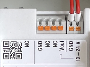
Connections as on the label:
- Vin - Supply voltage 12 - 24 Volt DC
- GND - Ground
- Vout - same as Vin
- A - Modbus ASCII/RTU line
- B - Modbus ASCII/RTU line
- GND - Ground
- ETH - Ethernet connection for LAN Uplink or Modbus TCP
- Connected cables must be between 0.05 mm² (AWG30) and 1.31 mm² (AWG16).
- Inserted cable length must be between 6mm and 7mm.
- Recommended wire termination:
- Weidmüller: H0,14/10 GR SV, Article Nr.: 9005180000, 8mm/6mm, max. AWG26
- All cables must only be connected or disconnected while the device is not powered
- Vout only supports small consumers like sensors with ≤ 1W
Power Supply
- Power supply via external mains adapter with 12 - 24 Volt DC
- Power output must be at least 2W and maximum 100W.
Radio (LoRa, FSK, NB-IoT, LTE Cat-M1)
|
|
|
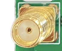
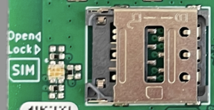
| Female SMA Connector | Antenna | Nano SIM (4FF) for mobile connectivity |
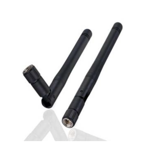
The antenna is used for different radio technologies based on LoRa, FSK including LoRaWAN® and wireless MBUS S1, C1/T1 Modes (868 MHz), OMS v3 & v4.
The same antenna is also used for communication via NB-IoT and LTE Cat-M1. A Nano SIM (4FF) is required for mobile connectivity.
The SIM Card must not be inserted or removed while the device is powered.
Properties of compatible SMA Antennas:
| SMA Joint Rod Antenna (LTE, LoRa) | |
|---|---|
| Frequency range | 698-960 / 1710-2700 MHz |
| Length | 108 mm |
| Antenna Gain | 2 dBi |
| V.S.W.R | <= 2.5 |
| Radiation | Omnidirektional |
| Polarisation | Vertical |
| Max. Power | 5 W |
| Impedance | 50 Ohm |
| Connector | SMA Male |
| Material of dome | TPE |
| Lobaro Article Nr. | 3000413 |
The device was only tested with the listed antenna. Lobaro does not take liability for the use with other antennas.
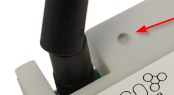
RESET-Button
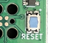
- Press the RESET Button to restart the deivce
- The RESET Button can be pressed through a small hole in the cover (e.g. with a paper clip). The position is marked with a ring on the label.
Config Port
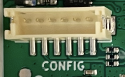
- The config port can only be reached when the cover is removed
- The configuration port is compatible with our 6-pin Lobaro USB Configuration Adapter (Arcticle Nr. 8000005).
- A free to use configuration tool can be downloaded from the Lobaro website.
LED
- Status information is visualized via the LED
Mobile operator and LTE band configuration
If you are using a different mobile operator than pre-configured, you should change the mobile operator code set in the Config Parameters Operator and (LTE) Band Operator codes are 5 digit codes that indicate country and operator.
For details about configuration for mobile network operation please refer to our article about Mobile Network Connection
Configuration
The device is shipped with default configuration parameters. The configuration can be changed via the 6-pin config port using the Lobaro USB Configuration Adapter.
More information about the usage of the configuration tools can be found in our documentation.
Remote Configuration is also supported after initial network connection.
Networking Parameters
| Name | Description | Default Value | Value Description & Examples |
|---|---|---|---|
WAN | Radio technology used for connection to backend | lte |
|
Host | Hostname / IP of the Lobaro Platform API Not used for LoRaWAN uplink | 94.130.20.37 | 94.130.20.37 = backend.lobaro.com |
Port | Port number of the Lobaro Platform API Not used for LoRaWAN uplink | 5683 |
NB-IoT Parameters (WAN = "lte", "nbiot", "ltem")
The LTE functionality is enabled if the WAN parameter is set to lte, nbiot, or ltem. Using this mode requires an appropriate SIM-Card to be inserted.
| Name | Description | Default Value | Value Description & Examples |
|---|---|---|---|
Operator | Mobile Operator Code (optional) | 26201 | 26201 (=Deutsche Telekom), for other operators, see above. |
Band | NB-IoT Band | 8 | "8", "20", "8,20", Empty = Auto detect (longer connecting time) |
APN | Mobile operator APN (optional) | iot.1nce.net | 1nce: iot.1nce.net Vodafone Easy Connect: lpwa.vodafone.com (l = littel L) |
PIN | SIM PIN (optional) | Empty or 4 digits (e.g. 1234) |
LoRaWAN Parameters (WAN = "lorawan", "lorawan-abp")
| Name | Description | Default Value | Value Description & Examples |
|---|---|---|---|
DevEUI | DevEUI used to identify the Device | Device's own DevEUI as printed on label | 8 bytes = 16 hex digits, e.g. 0123456789abcdef |
JoinEUI | EUI used for OTAA (aka AppEUI) | Individual default value for each device | 8 bytes = 16 hex digits, e.g. 0123456789abcdef |
AppKey | AES Key used for LoRaWAN | Individual default value for each device | 16 bytes = 32 hex digits, e.g. 0123456789abcdef001122334455667788 |
SF | Minimal Spreading Factor used | 12 | 7-12, used after reset, can be decreased by ADR during operation (but not increased) |
When changing the value for AppKey make sure you are using a good random source and keep the value secret. With this value it is possible to take control over the device when it reboots.
OTAA - Over the Air Activation
The preferred method to use LoRaWAN is Over The Air Activation (OTAA). When WAN="lorawan" the device uses the values to perform an OTAA Join with the LoRaWAN Network Server. Make sure the values for DevEUI, JoinEUI, and AppKey match.
ABP - Activation by personalisation
Our devices support activation by personalisation (ABP) when WAN="lorawan-abp". This mode is useful for devices that have a bad reception. You will have to synchronise session keys by hand between the device and your Network Server when using ABP.
TODO
LAN Parameters (WAN = "lan")
Connection via LAN/Ethernet is not supported, yet.
Coming soon!
Modbus related Parameters
| Name | Description | Default Value | Values Description & Examples |
|---|---|---|---|
MbCmd | List of Modbus Commands with Cron and Modbus parameters (see below). | 0 0/5 * * * *:R,9600,8N1:010300000003 | One or more entries of Modbus commands to be executed by the device. Each entry starts with a Cron expression defining when to execute the commands followed by the bus parameters used to address the Modbus slave devices. Each entry can contain multiple commands. See description below for a detailed explanation. |
† See also our Introduction to Cron expressions.
Modes of operation (work cycle)
Subject to change!
This chapter explains how the device works to collect and upload data.
- The device waks up at configured times to issue Modbus commands and forwards the responses to the Server via uplink message.
- Each uplink message can be responded from the server, e.g. to update configuration, update firmware or issue Ad-HOC Modbus commands.
- Regular status Uplink messages ensure, that the device is always reachable, even when no modbus command is scheduled.
Mobile data consumption
Uploading one uplink with 400 bytes including all metadata (might be less, depending on the configuration).
| Telegram upload interval | Monthly NB-IoT data usage |
|---|---|
| 1 each Day | ~12 kB |
| 8 each Day (every 3h) | ~100 kB |
| 400 each Week | ~700 kB |
| 250 each Day | ~3 MB |
All calculations are estimations and might vary depending on the configuration
The Lobaro Platform
The easiest way to work with the Lobaro Modbus Gateway is the Lobaro Platform. You can find it under https://platform.lobaro.com – Log in with the credentials provided by Lobaro.
Your Gateways should be listed under "Devices". If you have multiple devices in your account, you can distinguish them by the field "Address". The Address is printed on the box of the Gateway (the Address is the IMEI of the modem used by the device; that is the unique hardware address used for mobile communication).
Data messages
Data messages differ between LoRaWAN and LTE/LAN upload. While LoRaWAN messages are defined by Port and Byte pattern, LTE/LAN Uplinks are encoded as structured data (CBOR).
Since LoRaWAN uplinks are limited to ~50 Bytes some information that are avaliable on other transport might be skipped.
Coming soon!
For now please refer to our Modbus LoRaWAN Bridge - We try to keep the payloads similar.
CE Conformity
|
|
