New Version!
Sensors bought in 2022 or later are based on the Hybrid Industrial Gateways. You'll find all information about the configuration under Pressure Sensor Application.
Major changes:
- The new probes are based on Modbus (this version only supports I2C probes)
- Modbus enables cable length of more than 15m
- Uplink is supported for NB-IoT and LoRaWAN
Multiple different Variants
There are different kinds of Pressure Probes that use very different kinds of communication. As a consequence there exist different Variants of our Hardware for using Pressure Probes. Please take care that you only install the correct Variant of firmware on your device.
Consider using the latest firmware on your hardware
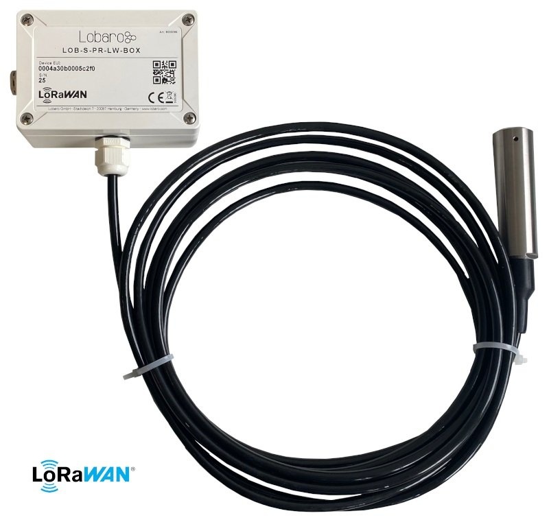
Target Measurement / Purpose
Precise liquid level measurement, e.g. for tanks, via LoRaWAN.
Features
- Cable length 15m
- 0…15 mH2O (15m water level, 1.5 Bar)
- Resolution: ± 0.5% FSO (Full Scale Output)
- Long term stability: ± 0.3% FSO per year
- Waterproof IP66 Housing
- Multi-year Battery life, ultra low power design
Order Information
- Type: LOB-S-PR-LW-BOX
- Articlenumber: 8000089
The (initial) configuration is normally done using our free Lobaro Maintenance Tool and the USB PC configuation adapter.
Beside this the configuration can also be changed or read remotely in the field using LoRaWAN downlink messages, see Downlinks description.
Specifications
- Measurement range: 0…15 mH2O (approx. 1.5 bar hydrostatic pressure)
- Accuracy: ± 0.5% FSO (Full Scale Output), ± 0.0075 Bar, ± 7.5mBar, ± 75mm, ±7.5cm
- Measuring principle: relative pressure measurement
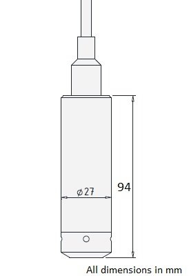
- 15m feed line incl. cable feedthrough
- Additional temperature sensor in probe head
- Power supply: 3.6V via JST XH connector
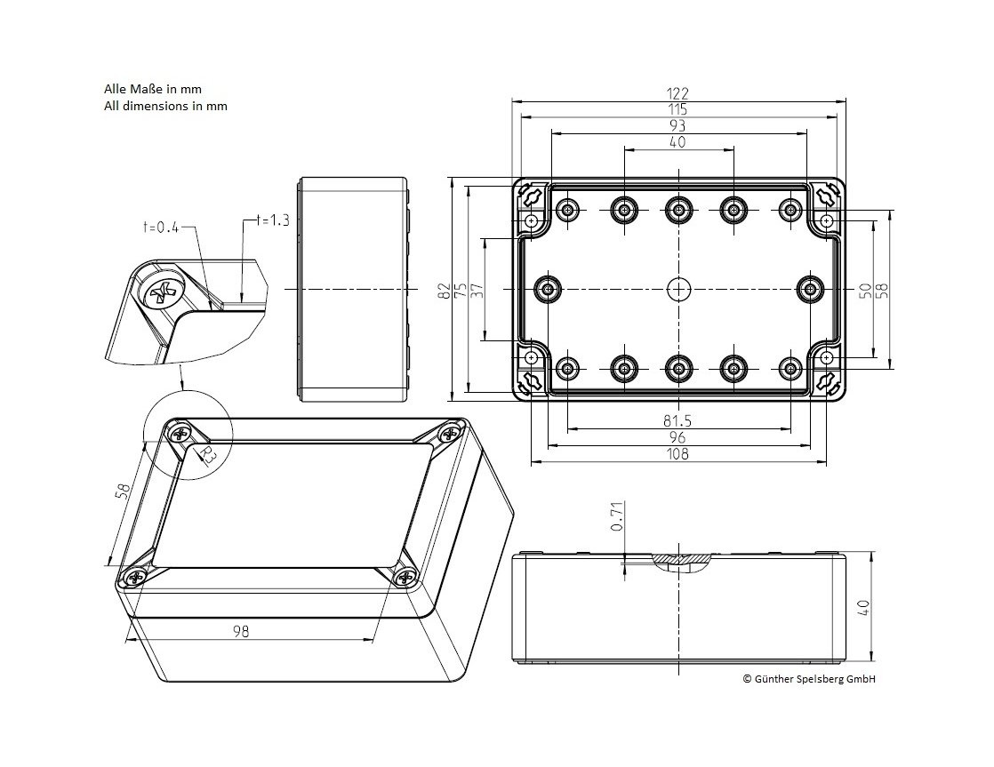
- Housing: IP67, 122 mm (l) x 82mm (b) x 55mm (h)
- Incl. pressure compensating element (DAE) for outdoor installation
- Quick release screws in housing
- Operating temperature: -10° C to +55° C
- Rel. Humidity 20 - 70 % fR, non-condensing
LoRaWAN Connection
Advanced Lobaro LoRaWAN Stack
Some of the features listed here (LoRaWAN 1.1, Remote Configuration, ...) are only implemented for recent versions of our firmware. For the Lobaro Sensor this starts with v0.2.1, for the Keller Sensor it starts with v0.3.0. If possible, you should update your devices to our most recent firmware.
The connection to the LoRaWAN network is defined by multiple configuration parameters. This need to be set according to your LoRaWAN network and the way your device is supposed to be attached to it, or the device will not be able to send any data.
For a detailed introduction into how this values need to be configured, please refer to the chapter LoRaWAN configuration in our LoRaWAN background article.
| Name | Description | Type | Values |
|---|---|---|---|
OTAA | Activation: OTAA or ABP | bool | true= use OTAA, false= use ABP |
DevEUI | DevEUI used to identify the Device | byte[8] | e.g. 0123456789abcdef |
JoinEUI | Used for OTAA (called AppEUI in v1.0) | byte[8] | e.g. 0123456789abcdef |
AppKey | Key used for OTAA (v1.0 and v1.1) | byte[16] | |
NwkKey | Key used for OTAA (v1.1 only) | byte[16] | |
SF | Initial / maximum Spreading Factor | int | 7 - 12 |
ADR | Use Adaptive Data Rate | bool | true= use ADR, false= don't |
TimeSync | Days after which to sync time | int | days, 0=don't sync time |
RndDelay | Random delay before sending | int | max seconds |
RemoteConf | Support Remote Configuration | bool | true=allow, false=deactivate |
LostReboot | Days without downlink before reboot | int | days, 0=don't reboot |
Configuration
Configuration values defining the behaviour of the device. The Min and Max values will be preconfigured when receiving the device. In case of using "Restore Default" they will be reset to standard values and have to be set again using the values printed on the sensor or given separately.
| name | description | example value |
|---|---|---|
sendCron | Cron expression defining when to read and send | 0 0/15 * * * * for every 15 minutes |
rangeMin | min range in mh2o | in most cases 0 |
rangeMax | max range in mh2o | in most cases 15 |
outputMin | min digital output value of the sensor | in most cases 819 |
outputMax | max digital output value of the sensor | in most cases 11664 |
See also our Introduction to Cron expressions.
Payload Format
Data Message
Port: 1, Payload: 8 Bytes
This message is sent everytime the cron expression given in the configuration triggers.
Non ADC-Values in the data message are encoded as little endian. The format is as follows:
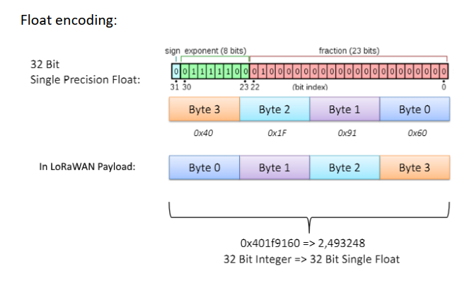
PPPPTTVVppttMMMM
PPPP: 00-03: 4 Byte, float32 LE, Pressure in Bar (for float encoding see image below)
TT:   04-05: 2 Byte, int16 LE,   Temperature in the sensor probe in 1/100°C
VV:   06-07: 2 Byte, uint16 LE,  Supplyvoltage in the Device measured in mV
pp:   08-09: 2 Byte, uint16 BE,  Raw Pressure ADC value (no Unit) (since v0.3.3)
tt:   10-11: 2 Byte, uint16 BE,  Raw Temperature ADC value (no Unit) (since v0.3.3)
MMMM: 12-13: 4 Byte, float32 LE, Level in meter H2O(for float encoding see image below) (since v0.3.3)
NOTE
- 1.0 Bar approx. 10m water above probe
- 0.1 Bar approx. 1m water above probe
- Online converter: https://www.convertunits.com/from/bar/to/meters+head
To give an example (with bytes coded in hex):
cf91873b56076a0e

PPPP: cf91873b -> 0.004137254785746336 -> 0.0041 Bar (~41mm water level)
TT:   5607 -> 0x0756 -> 1878 -> 18.78°C
VV:   6a0e -> 0x0e6a -> 3690 -> 3.69V
Status message
Port: 64, Payload: 13 Bytes
The Status Message communicates information about the device itself (starting with firmware 0.3.0). It contains information like the internal temperature of the device and the reason for the latest reboot. It is uploaded once a day along the data message uploads.
Values in the status message are encoded as big endian. The format is as follows:
PPBvvvSRFTTVV
PPB: 00-02: 3Byte, ASCII,     Firmware Identifier, constant 'PPB'
vvv: 03-05: 3Byte, uint8,     Firmware Version, e.g. 0.3.1
S:   06-06: 1Byte, uint8,     Status/Error condition, coded
R:   07-07: 1Byte, uint8,     Reboot Reason, coded
F:   08-08: 1Byte, uint8,     Final words, coded
VV:  09-10: 2Byte, uint16 BE, VCC in mV
TT:  11-12: 2Byte, int16 BE,  internat device's temperature in 1/10°C
To give an example (with bytes coded in hex):
5050420003010006000e6a00d0

505042 -> Firmware identifier 'PPB'
000301 -> Firmware version 0.3.1
00     -> 0 -> Status "OK"
06     -> 6 -> Reset reason: EXTERNAL_RESET_PIN_RESET
00     -> 0 -> No final words
0e6a   -> 3690 -> 3.69V supply Voltage
00d0   -> 208 -> 20.8°C internal Temperature
Status Code
The status code indicates problems the device has detected. The possible values are:
| Hex | Dec | Name | Explanation |
|---|---|---|---|
0x00 | 0 | OK | No problems detected |
0x65 | 101 | PROBE_ERROR | Device failed to communicate with the pressure probe |
Reset Reason Code
The reset reason reports what triggered the latest reboot (which might have happend month ago).
| Hex | Dec | Name |
|---|---|---|
0x01 | 1 | LOW_POWER_RESET |
0x02 | 2 | WINDOW_WATCHDOG_RESET |
0x03 | 3 | INDEPENDENT_WATCHDOG_RESET |
0x04 | 4 | SOFTWARE_RESET |
0x05 | 5 | POWER_ON_RESET |
0x06 | 6 | EXTERNAL_RESET_PIN_RESET |
0x07 | 7 |
|
Final words
currenctly not used in this firmware.
Supply voltage
The device measures the voltage of its power supply. This is useful for diagnosing the state of the battery.
The voltage is sent as a big endian unsigned 16 bit value measuered in mV.
- Maximum Voltage: 3.7 V
- Minimum Voltage: 2.6 V
Temperature
The device has an on board temperature sensor, to help diagnosing failures. This is a different temperature sensor than the one used for the data message, which is meassured by the attached probe!
The temperature is sent as a big endian signed 16 bit value measured in tenth of °C.
Payload Parser
Our reference JavaScript parser can be found at github. It works for our Lobaro Backend, The Things Network (TTN), ChirpStack (ex LoRaServer) and niota.io (Digimondo)
Reference Parser: https://github.com/lobaro/lobaro-parsers/blob/master/water-level-sensor/decoder.js
There also exists a parser for Element-IoT (by Zenner IoT):
Element-IoT: https://github.com/ZennerIoT/element-parsers
Device & Probe Dimensions
CE Declaration of Conformity
CE Declaration of Conformity (pdf).