The Lobaro Wireless M-Bus NB-IoT Gateway V2.
THIS PRODUCT HAS BEEN FUNCTIONALLY REPLACED BY ITS SUCCESSOR (LOB-GW-HYB-WMBUS) AND WILL NO LONGER BE PRODUCED.
![]()
- Order number: 8000131
- Type: LOB-GW-WMBUS-NB2
Successor available
This device is no longer available for sale and has been replaced by Wireless M-Bus Gateway V3 since 12/2021.
Overview
The Lobaro Wireless M-Bus Gateway V2 is a simple to use, cost and energy efficient device that receives, caches and forwards metering consumption data from up to 500 Wireless M-Bus enabled devices, like water meters, electricity meters, heat meters onto the Internet.

The gateway collects data from all metering device conforming to the 868 MHz Wireless M-Bus standard (EN 13757-4) or uses Sensus RF Bubble UP low power short range FSK radio modulation to broadcast consumption data. Their wireless range is typically only about 50m with this traditional technology. The Lobaro Wireless M-Bus Gateway extends this range by collecting the short range data and then uploads it using modern cellular IoT networks (Narrowband IoT) onto the Internet. Alternatively an additional upload path via LoRaWAN networks is available. This unique feature of combining to LPWAN technologies in a single device might be used as a fallback if yet no modern NB-IoT network is available at the place of deployment.
Metering data is send to the Lobaro Platform, were it gets parsed, displayed and made available for further processing. Because most Wireless M-Bus telegrams are encrypted, the Platform allows adding decryption keys for individual meters, so that the data can be decrypted by the Platform. It is also possible to use the Lobaro Wireless M-Bus Gateway without the Platform and connect it to your own backend, if it is capable of parsing and decrypting wMBus telegrams.
LoRaWAN® is a mark used under license from the LoRa Alliance®.
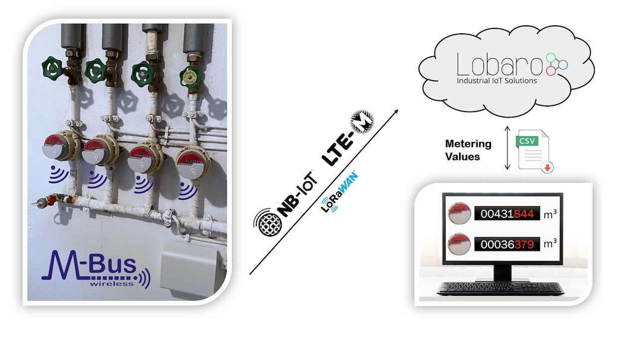
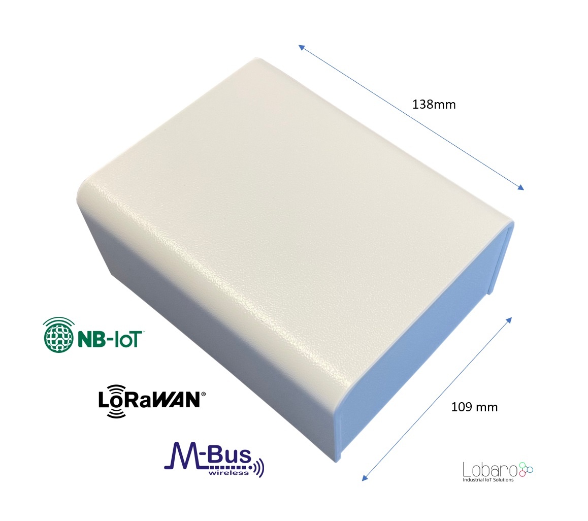
Note: The Lobaro IoT platform is fully optional! Image shows product with design cover accesssory.
Basic work cycle
Quick start guide
- Make sure SIM card and battery are correctly connected.
- Go to The Lobaro Platform and log into your account.
- Go to "Devices" and select your "Lobaro NB-IoT wMBus Gateway".
- If you have several Gateways: the "Address" is printed on the device's case.
- You should see all wMBus Telegrams the Gateway collected so far.
- If the data is encrypted (closed lock symbol 🔒), you can add keys for your devices under "Organisation → wMbus".
- Push the reset button inside the device, if you want to trigger data collection (will take several minutes).
Compatible meters
The Lobaro wMBUS Gateways are working with every meter using standard 868 MHz wMbus:
- wireless MBUS S1, C1 or T1 mode (unidirectional 868 MHz modes following DIN EN 13757-4)
- Open metering specification (OMS) v3 & v4
- Sensus RF Bubble UP - Manufacturer specific radio protocol
For more details please refer to our Wireless M-BUS article on doc.lobaro.com.
Setting up the device
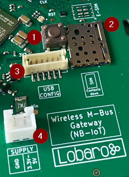
- RESET Button
- SIM Card Holder (Nano SIM, 4FF)
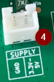
- Connector for Lobaro USB-Config Adapter (Config, Logs, Firmware Updates)
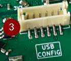
- 2-Pin JST XH Stecker (3.3 - 5V, e.g. for 3.6V Battery)
SIM card

A SIM card is needed by the Gateway to connect to the mobile network. The drawing on the PCB displays the correct orientation of the SIM. The contacts must face down.
We can recommend 1nce.com for NB-IoT Connectivity. The device supports all Providers on Band 8 and Band 20.
Power supply
The Gateway is powered by a 3.6V D-Cell battery, that is connected via a XH connector (a white 2 pin socket on the board, labeled "VBat 3V6"). If the battery is initially not connected to the board, you will need to plug in the XH connector. When the device powers up, the on-board LED will blink green once.
Resetting the device

Inside the device on the board is a button labeled "RESET". If you push this button while the device is running, it will stop and reboot. You should see a green flash of the LED when the device starts again. Disconnecting the battery from the device will not be enough to reboot the device! The Gateway buffers enough energy to run for several minutes without a power supply connected (the actutal time is depending on what the Gateway does during that time).
Configuring the device
If you purchased your Lobaro wMBus Gateway with a SIM card included and you are using the Lobaro Platform, you will not need to change any configuration for the device to work. Instructions on how to change the device's configuration using the Lobaro Config Adapter can be found on the Device Configuration on the manual page for our Configuration Tool.
Mobile operator and LTE band configuration
If you are using a different mobile operator than pre-configured, you should change the mobile operator code set in the Config Parameters Operator and (LTE) Band Operator codes are 5 digit codes that indicate country and operator.
For details about configuration for mobile network operation please refer to our article about LTE / NB-IoT Networks
Configuration
The configuration can be read or changed locally via USB and the Lobaro Maintenance Tool or remotely using the Lobaro IoT Platform (NB-IoT only).
Configurations of up to 5000 bytes are supported, which enables a Device-Whitelist of up to 500 Meter-IDs.
General Parameters
| Name | Description | Default Value | Value Description & Examples |
|---|---|---|---|
WAN | Radio technology used for data uploads | lte | "lte": use cellular NB-IoT for uplinks "lorawan": use LoRaWAN for uplinks (working like Wireless M-Bus Bridge V2) |
NB-IoT Parameters (WAN = "lte")
The NB-IoT functionality is enabled if the WAN parameter is set to "lte". A SIM-Card has to inserted.
| Name | Description | Default Value | Value Description & Examples | |
|---|---|---|---|---|
Host | Hostname / IP of the Lobaro Platform API | 94.130.20.37 | 94.130.20.37 = backend.lobaro.com | |
Port | Port number of the Lobaro Platform API | 5683 | ||
UdpHost | Separate IP to upload plain telegrams via UDP | optional, empty = upload to Lobaro IoT Platform | ||
UdpPort | Separate Port to upload plain telegrams via UDP | 0 | only used when UdpHost is set | |
Operator | Mobile Operator Code | 26201 | 26201 (=Deutsche Telekom), for other operators, see above. | |
Band | NB-IoT Band | 8 | "8", "20", "8,20", Empty = Auto detect (longer connecting time) | |
APN | Mobile operator APN | iot.1nce.net | 1nce: iot.1nce.net Vodafone Easy Connect: lpwa.vodafone.com (l = littel L) | |
PIN | SIM PIN (since v0.7.0) | Empty or 4 digits (e.g. 1234) | ||
UseNbiot | Try to connect with NB-IoT | true | ||
UseLtem | Try to fallback to LTE-M when supported by the Modem | false |
LoRaWAN (WAN = "lorawan")
![]() The LoRaWAN functionality is enabled if the
The LoRaWAN functionality is enabled if the WAN parameter is set to "lorawan". In this mode the device behaves like the LoRaWAN only "Wireless M-Bus Bridge V2", consider also reading its manual when using the LoRaWAN functionality of the Wireless M-Bus Gateway V2 (NB-IoT). No SIM-Card is needed.
The connection to the LoRaWAN network is defined by multiple configuration parameters. This need to be set according to your LoRaWAN network and the way your device is supposed to be attached to it, or the device will not be able to send any data.
For a detailed introduction into how this values need to be configured, please refer to the chapter LoRaWAN configuration in our LoRaWAN background article.
| Name | Description | Default Value | Values |
|---|---|---|---|
OTAA | Activation: OTAA or ABP | true | true= use OTAA, false= use ABP |
DevEUI | DevEUI used to identify the Device | e.g. 0123456789abcdef | |
JoinEUI | Used for OTAA (called AppEUI in v1.0) | e.g. 0123456789abcdef | |
AppKey | Key used for OTAA (LoRaWAN v1.0.x and v1.1) | ||
NwkKey | Key used for OTAA (LoRaWAN v1.1 only) | ||
TimeSync | Days after which to sync time over LoRaWAN | 3 | days, |
RndDelay | Random delay before sending (avoids collisions) | 10 | max seconds |
PayloadFormat |
| 0 | For details see manual of wMBUS LoRaWAN bridge |
LostReboot | Days without downlink before reboot | 5 | days, 0=never reboot |
Metering reception Parameters
| Name | Description | Default Value | Default Values & Examples |
|---|---|---|---|
listenCron | Cron expression defining when to receive wMBUS | 0 0 12 * * * |
|
cmodeDurSec | Duration (Seconds) of wireless M-Bus C1/T1-mode receive | 300 | 0= Do not collect C1/T1 mode |
smodeDurSec | Duration (Seconds) of wireless M-Bus S1-mode receive | 0 | 0= Do not collect S1 mode |
xmodeDurSec | Duration (Seconds) of Sensus RF receive | 0 | 0= Do not collect Sensus RF telegrams |
mFilter | wMBus manufacturer filter sep. by , e.g. dme,itw (Comma separated list WITHOUT spaces) | blank=no filter, | |
typFilter | meter device type filter e.g. 08,07 for Heat Cost and Water (Comma separated list WITHOUT spaces) |
| |
devFilter | meter id filter e.g.
Up to 500 wMBus-IDs or 400 Sensus-RF-IDs are supported. | blank=no filter | |
ciFilter | Collect only telegrams with specific values in the ci-Field, must we written as 2 hex digits (with leading zeros).
| blank=no filter, | |
maxTelegrams | Set hard limit on how many telegrams will be collected and uploaded. The bridge will stop collection, once this number has been collected, regardless of the passed time. Can be used save battery / data volume, should the device be in an area with a large number of meters. Set to | Since v0.8.5 |
† See also our Introduction to Cron expressions.
Modes of operation (work cycle)
This chapter explains how the device works to collect and upload wireless Mbus data.
- Wakup at
listenCron / On start up of device ignore listenCron always run following steps. - Collect C-Mode and T-Mode telegrams for
cmodeDurSec(if not 0) Collect S-Mode telegrams for
smodeDurSec(if not 0)- Collect X-Mode telegrams (Sensus RF) for x
modeDurSec(if not 0) - Upload all stored data via NB-IoT / LTE-CatM1 or LoraWAN (see "WAN" configuration)
- When the upload fails the upload is retried every 24h or until the next
listenCrontrigger.
- When the upload fails the upload is retried every 24h or until the next
- Sleep till next
listenCronor status telegram upload.
Deduplication
When collecting wMbus telegrams, duplicates are always replaced by the latest telegram in memory. This leads to only 1 Telegram per Type and Meter per upload phase.
A telegram is considdered a duplicate when all of the following criteria match:
- The actual length of the telegram is the same
- The ID is the same
- The CI-Field is the same
Mobile data consumption
Uploading one wMbus telegram consumes approximately 400 bytes data including all metadata.
| Telegram upload interval | Monthly NB-IoT data usage |
|---|---|
| 1 each Day | ~12 kB |
| 8 each Day (every 3h) | ~100 kB |
| 400 each Week | ~700 kB |
| 250 each Day | ~3 MB |
All calculations are estimations and might varry depending on the configuration
The Lobaro Platform
The easiest way to work with the Lobaro wMBus NB-IoT Gateway is the Lobaro Platform. You can find it under https://platform.lobaro.com – Log in with the credentials provided by Lobaro.
Your Gateways should be listed under "Devices". If you have multiple devices in your account, you can distinguish them by the field "Address". The Address is printed on the box of the Gateway (the Address is the IMEI of the modem used by the device; that is the unique hardware address used for mobile communication).
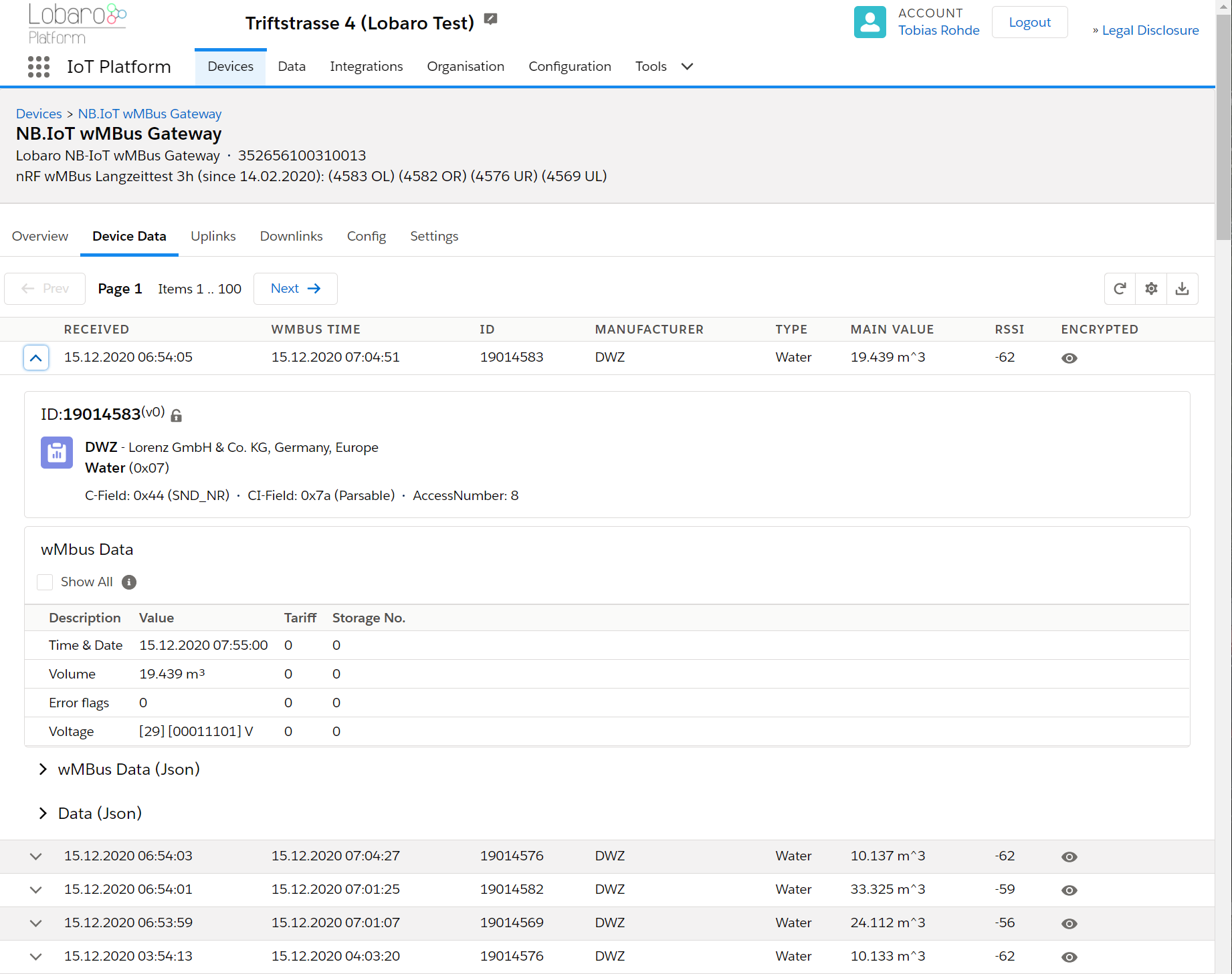
Displaying wMBus data
Open the tab "Device Data" to see a list of all Wireless M-Bus telegrams that your Gateway uploaded.
Changing configuration
You can see and edit the configuration of the Gateway without physical access to the device from the Lobaro Platform. Open the tab "Config" for your device. The current configuration will be shown. You can edit individual config entries by clicking on the pencil. After you entered all the values you want to change, click the "Update config" button. The new configuration will be sent to the device the next time it uploads data to the platform. After changing the configuration, it will reboot and start working with the new config.
The remaining configuration parameters (Host, Port, APN, Band, ...) are used to configure the way the device connects to the mobile provider and to the Lobaro Platform. There is no need to change these values when using the Gateway with the Lobaro Platform.
wMBus encryption Keys
Many meters are sending encrypted data. In order to get the values out of that encrypted telegrams, you will need to provide the decryption key to the Platform. Go to "Organisation" / "wMBus" to add encryption keys. You will need to set a key for a specific meter (identified by its ID).
Once a key is entered for a device, any telegram received after that will be decrypted and listed in clear text under "Device Data".
Forwarding data to your own system
If you want the received data inside your own system, you can add an Integration inside the Lobaro Platform that forwards all data to your system. We currently supply a REST API that allows you to query data from our platform actively, as well as a HTTP(S) integration, that pushes incoming data to your system when it is received.
Configuration with the Config Adapter
Instead of using the Lobaro Platform, you can use the Lobaro Config Adapter and the Config Tool to change the Configuration directly in your hardware. This can be useful when you want to change configuration while the mobile connection does not work (or if you do not want to use the Lobaro Platform). See Lobaro USB configuration adapter for more information.
Using Raw UDP
In default configuration, the Gateway communicates using CoAP with messages that are designed to work with our Lobaro Platform as a backend. If you want to connect the Gateway directly to your own backend, it can be hard to implement an endpoint.
CBOR messages over UDP
Starting with Firmware version 0.5.0, the Gateway supports a second format, where wMBus telegrams are uploaded without CoAP over UDP. When the configuration Parameters UdpHost and UdpPort are set to a destination (IP address and port number), wMBus telegrams will be sent to that destination instead of the Lobaro Platform. It will be sent as a CBOR object using raw UDP packets without CoAP. CBOR can easily be parsed in most programming languages using existing libraries. It is similar to JSON but uses a binary representation.
Limitations of UDP
Because UDP has no validation mechanism, there will be no retransmission in case of packet loss. You will be able to spot missing packets by gaps in the frame number. When implementing this, please keep in mind, that UDP packets are not guaranteed to arrive in the order they are sent.
You can find CBOR decoders for variaous programming lanuages, see: https://cbor.io/
Or you can use the online decoder for debugging at http://cbor.me/ (Paste data into the right column and press the green arrow above to decode)
BF61696F333532363536313030343631373734616E19013C6164BF676D6F6E69746F727891636F6E6E65637465643A312C20636F6E4D6F64653A312C207265673A352C207461633A444144392C2063693A30313938374330462C2070736D3A31313130303030302C207461753A30313031313131312C20525352503A353028322F34292C20525352513A323328332F34292C20534E523A333528332F34292C20636F6E54696D653A31362C20636F6E4661696C733A306374616364444144396263696830313938374330466472737270183264727372711763736E7218236370736D683131313030303030637461756830313031313131316476626174190DE36B74656D706572617475726518966974696D657374616D701A5FC74A6E6874656C656772616D58B2B144C5147423900103067274239001C5140006830090256C9AED3F524DB6D103E888AE94F5E5F6C0A5ACDF4D51BB31522543145770CF44BD7FC1865F0ABEFC15EE296D38C710B0CDC518FDFF89FF87DCA6F357490E60AB07697C121CD6794A196A3A705D6FA2D25169C9C204156AD221E8F0829AE221C74EA92ED4DC65014178730E2A2313C0C879A6FB19D9B8F50E6EA2DBF721C560041AB1AFA874D24F49059981946D937DE103FD0C02032102FD0B01116472737369385AFFFFFF
{"i": "352656100461774", "n": 316, "d": {"monitor": "connected:1, conMode:1, reg:5, tac:DAD9, ci:01987C0F, psm:11100000, tau:01011111, RSRP:50(2/4), RSRQ:23(3/4), SNR:35(3/4), conTime:16, conFails:0", "tac": "DAD9", "ci": "01987C0F", "rsrp": 50, "rsrq": 23, "snr": 35, "psm": "11100000", "tau": "01011111", "vbat": 3555, "temperature": 150, "timestamp": 1606896238, "telegram": h'B144C5147423900103067274239001C5140006830090256C9AED3F524DB6D103E888AE94F5E5F6C0A5ACDF4D51BB31522543145770CF44BD7FC1865F0ABEFC15EE296D38C710B0CDC518FDFF89FF87DCA6F357490E60AB07697C121CD6794A196A3A705D6FA2D25169C9C204156AD221E8F0829AE221C74EA92ED4DC65014178730E2A2313C0C879A6FB19D9B8F50E6EA2DBF721C560041AB1AFA874D24F49059981946D937DE103FD0C02032102FD0B0111', "rssi": -91}}
The "telegram" part can be decoded using our wMbus Parser API at https://platform.lobaro.com/#/wmbus/parser
Controlling the device
When UdpHost and UdpPort are set while Host and Port are referring to the Lobaro Platform, the Gateway will upload the wMBus telegrams to the UDP destination but will also sent diagnostic messages to the Platform. In this configuration you can still use the features of the Lobaro Platform to control the device for configuration changes or firmware updates, while receiving your wMBus data directly to your own backend.
Format
Schema
The CBOR object contains the following information
{
    "d": {
      "rssi": <int: RSSI>,
      "vbat": <int: Supply voltage in mV>,
      "monitor": <string: human readable diagnostic information>,
      "telegram": <bytes: wmbus telegram>,
      "timestamp": <int: unix timestamp, time of reception>,
      "temperature": <int: device temperature in 1/10°C>
    },
    "i": <string: device's IMEI>,
    "n": <int: frame number>
}
| Name | Explanation |
|---|---|
rssi | Received signal strength indication indicating the quality of the received signal. |
vbat | Supply voltage to the Gateway, measured in millivolts (mV). |
monitor | Human readable diagnostic string. The format of this information subject to change and should not be relied on. |
telegram | Bytes of the received wMBus telegram as a byte string. |
timestamp | Time of reception of the telegram in the gateway, given as a Unix Timestamp. |
temperature | Temperature inside the Gateway, measured in tenth of Degree Centigrade (d°C). |
i | IMEI of the Gateway's Modem, uniquely identifying the Device. |
n | Frame number. Starts at 1 for the first UDP-upload after boot and is increased for every upload. |
Example
The following shows an example message if you display it as JSON. In the CBOR object, the telegram is stored as a byte string. Because JSON does not support binary data, in this example it is encoded using base64.
{
    "d": {
      "rssi": -99,
      "vbat": 3688,
      "monitor": "connected:1, conMode:1, reg:5, tac:D71E, ci:019C1307, psm:11100000, tau:00001100, RSRP:56(2/4), RSRQ:24(3/4), SNR:37(3/4), conTime:3, conFails:0",
      "telegram": "SUSTRHkFAYg0CHgN/181AIJnADXIv1WtPFse1mYcZZQLiPR/aujF9e46meEB6CIkxJmHUEd6xPdAmop3uqIt4yWMgbwEbToKiCc=",
      "timestamp": 1594201536,
      "temperature": 240
    },
    "i": "123456101550542",
    "n": 7
}
Explanation:
UDP-Uplink #7 from Gateway with IMEI 123456101550542
Status of Gateway during upload:
  internal Temperature: 24.0°C
  supply Voltage: 3.688V
  Mobile provider, Cell-ID: 019C1307
Received wMBus Telegram:
  time of recept: 2020-07-08T09:45:36 (UTC)
  telegram (as hex): 49449344790501883408780dff5f350082670035c8bf55ad3c5b1ed6661c65940b88f47f6ae8c5f5ee3a99e101e82224c4998750477ac4f7409a8a77baa22de3258c81bc046d3a0a8827
  rssi: -99
LED blinking patterns
The device has an RGB-LED to give visual feedback.
The blinking patterns are not final and will be revised in a future version of the firmware!
On boot, the device shortly flashes the LED green.
| When | Pattern | Explanation |
|---|---|---|
| on reset | short green flash every ~15s | Configuration is invalid |
| on reset | short green flash every ~25s | SIM-Card cannot be read |
| during operations | blue on/off once per second | Trying to connect to mobile provider |
| during operations | blue on/off once per second, then green | Trying to connect to mobile provider, success |
| during operations | blue on/off once per second, then red | Trying to connect to mobile provider, failing |
Housing Specification & Accessories

The Lobaro wireless Mbus bridge uses the TG PC 1208-6-o feature rich IP67 housing from Spelsberg.
For the housing the following accessories are available on request:
Housing Design Cover
For a cleaner look of the device a addon design cover is available. Order number: 8000140
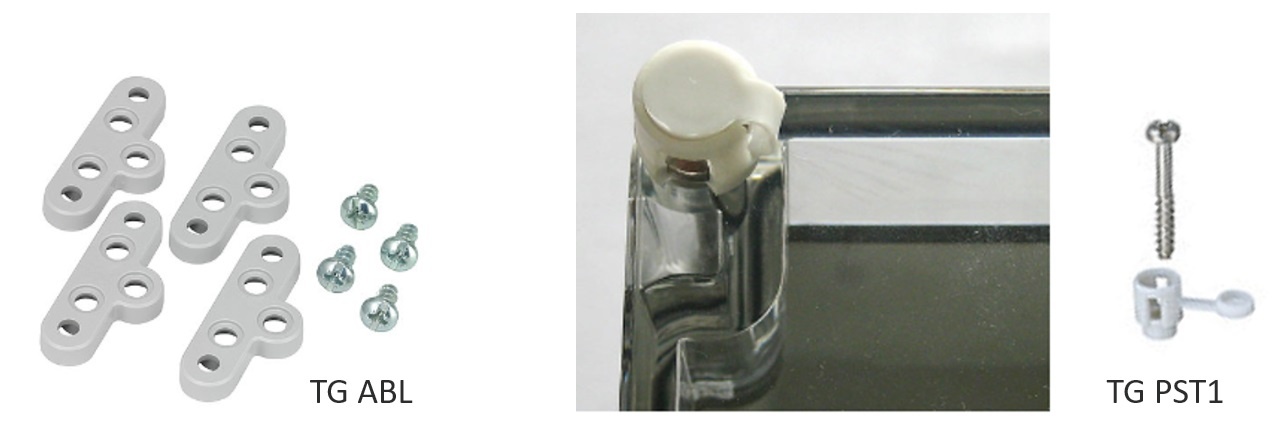
External fixing lugs (TG ABL):
Allow the mounting without opening the (sealed) cover. Order number: 3000104
Sealing kit (TG PST1):
May be used to seal the box to complicate unauthorized access to the device.
Troubleshooting
I did not get a username/password for the Lobaro Platform.
Please contact contact Lobaro to get your account information.
I do not see my Gateway listed unter "Devices".
It is possible that the purchased device has not been added to your account. Please check if you got an Activation Code with your hardware. If so, you can enter it under "Tools" / "Hardware Activation" in order to claim the device for your account.
I cannot find data for my specific meter.
Make sure your Gateway collected data since you brought it close to the meter (check timestamps on data). With standard configuration, it only collects data every 8 hours. You can press the "RESET" Button inside the device to make it reboot and start collecting data.
Also check the specifications of your wMBus meter. How often does it send data? What mode does it use? Using standard configuration, the wMBus Gateway only collects C-Mode and T-Mode telegrams. If your meter is sending S-Mode, you will need to change the Gateway's configuration.
Data for my meter only shows "Payload encrypted".
Most meters encrypt the data they are sending out (information about water/energy usage is personal data). In order to see values from encrypted wMBus telegrams, your will need to supply the decryption key for your meter (you should be able to get the key where you got the meter). You can add the key in the Lobaro Platform under "Organisation" / "wMBus". You will have to add a key for a specific meter (identified by the meter's ID).
After you supplied the key, new telegrams that are received should be decrypted so that you can see the values inside the telegram.
How can I check the NB-IoT Signal quality?
Signal quality comes from the Modem Monitor string: "RSRP:13(0/4), RSRQ:5(0/4), SNR:19(1/4)"
The monitor string is send together with some uplink messages, the raw values (as integer) are also send inside the status message.
{
    "d": {
      "ci": "00B00A00",
      "psm": "00000000",
      "snr": 25, // <<<<<<<<<<
      "tac": "000",
      "tau": "00000000",
      "rsrp": 32,  // <<<<<<<<<<
      "rsrq": 17,  // <<<<<<<<<<
      "vbat": 3590,
      "temperature": 200
    },
    "i": "111111111111111",
    "n": 3,
    "q": "status"
  }
- RSRP = Signal Power
- RSRQ = Signap Quality
- SNR = Signal to Noise Ratio
Do decode the values please reffer to the nRF9160 Knowledge Base
<rsrp>
- 0 – RSRP < −140 dBm
- 1 – When −140 dBm ≤ RSRP < −139 dBm
- 2 – When −139 dBm ≤ RSRP < −138 dBm
- ...
- 95 – When −46 dBm ≤ RSRP < −45 dBm
- 96 – When −45 dBm ≤ RSRP < −44 dBm
- 97 – When −44 dBm ≤ RSRP
- 255 – Not known or not detectable
<rsrq>
- 0 rsrq < −19.5 dB
- 1 – When −19.5 dB ≤ RSRQ < −19 dB
- 2 – When −19 dB ≤ RSRQ < −18.5 dB
- ...
- 32 – When −4 dB ≤ RSRQ < −3.5 dB
- 33 – When −3.5 dB ≤ RSRQ < −3 dB
- 34 – When −3 dB ≤ RSRQ
- 255 – Not known or not detectable
Safety Instructions
Read and follow all relevant safety instructions
- Sicherheitshinweise / Safety instructions (DE / EN)
- WEEE Disposal / Entsorgung von Geräten von Lobaro