Product Identification
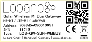
| Type | LOB-GW-SUN-WMBUS |
| Name | Solar Wireless M-Bus Gateway |
| Order number | #8000179 |
Overview
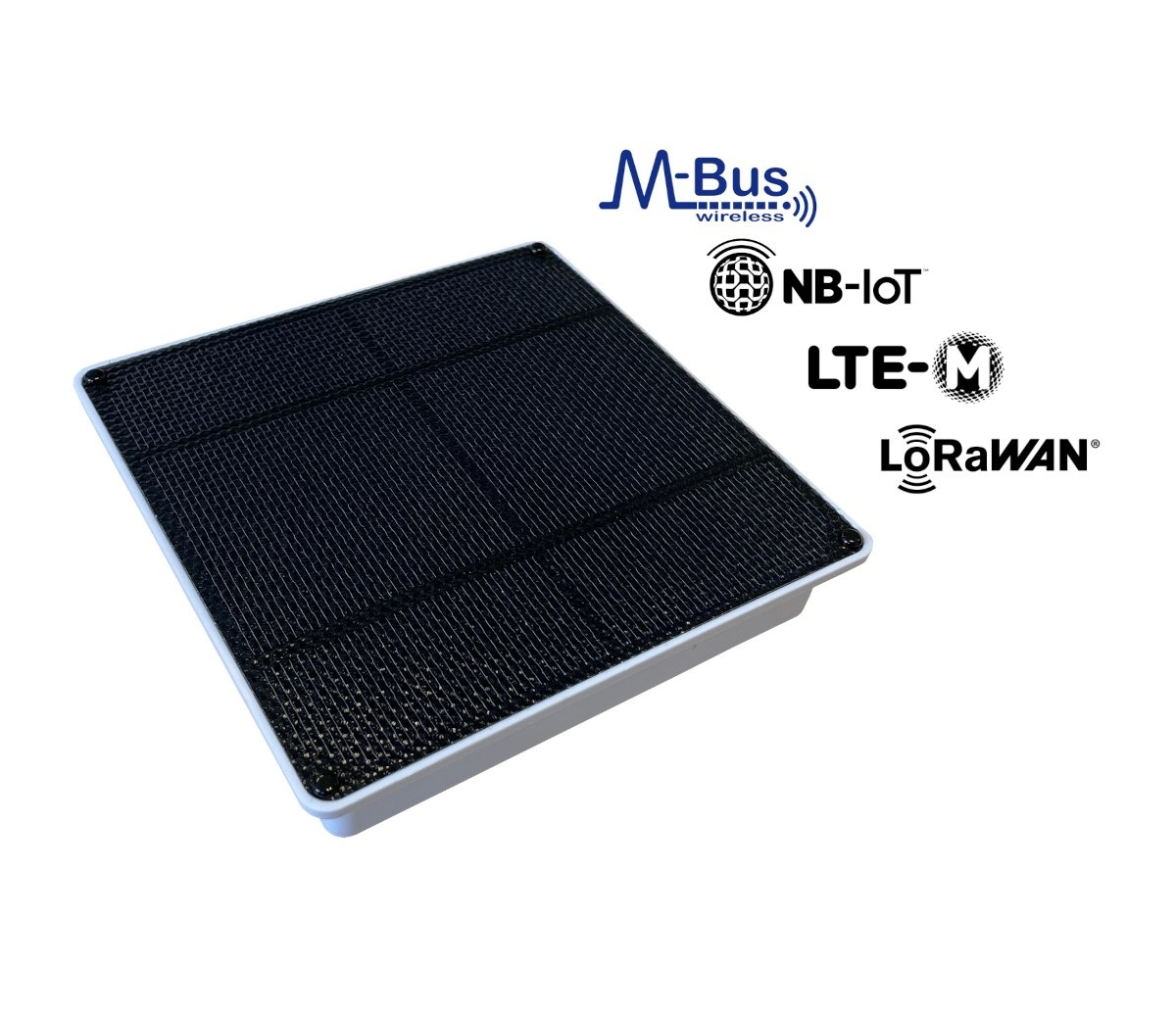
The maintenance-free Lobaro Solar Wireless M-Bus Gateway collects consumption data from up to 500 commercially available water meters, heat meters, heat cost allocators, etc. with 868 MHz wireless M-Bus radio interface or Sensus RF Bubble Up and forwards them regularly encrypted via NB-IoT or LTE-M1 mobile radio or LoRaWAN to the Internet for daily or frequent evaluation.
Thanks to the 100% battery-free design and the permanent power supply by the integrated high-performance solar cell, meter data can be transmitted several times a day in many applications when mounted with daylight incidence. The achievable readout intervals can, with a suitable installation location, be many times higher than with our battery-powered variant and there are no costs for battery changes. In addition to the application for billing purposes, this innovative design also enables novel areas of application in the field of predictive maintenance.
Quick Start
Differences to battery powered variant
IMPORTANT
This device differs from the battery powered variant in the following ways:
- The device can't be opened in any way - It was sealed with glue during production to achieve high waterproofing for outdoor use.
- A LTE-M / NB-IoT SIM card has been already inserted by Lobaro. Please contact Lobaro if your own sim cards should be inserted during production before sealing.
- The only kind of configuration adjustment can be done via the Lobaro platform or LoRaWAN downlinks. The USB cable option is not available.
- The device is shipped in standby mode. Before first use, it must be activated via the magnetic contact on the housing indicated by a dot.
- The device uses an audio buzzer instead of an LED for feedback on power level and operating status.
- The default WAN selection is "LTE". Please use the Lobaro Platform to switch to LoRaWAN if this is the needed uplink technology.
Initial Startup
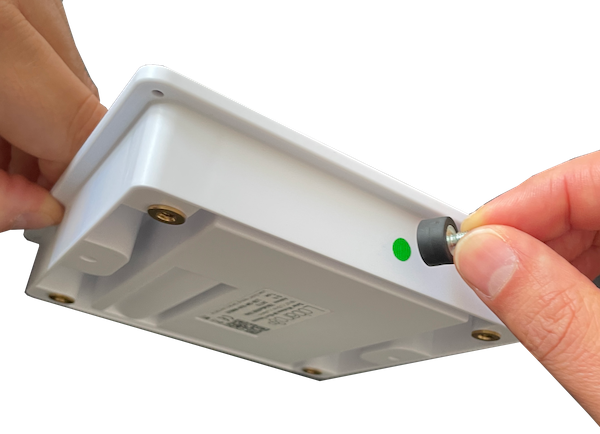
- Shortly (< 1 second) hold an magnet to the dot marking on the housing
- Release the magnet
- The devices indicated the current power level by audio (3-0 range, 3 beeps = fully charged)
- If the device is in "standby" mode a descending tone is played after the energy level audio indication
- If the level is not 3 or at least 2 place the device in a position with daylight incidence for some hours and check again later (1)
- To reset the device hold the magnet for 5 seconds+ to the dot marking
- A rhythmic on/off tone sounds until three fast beeps indicate the device reset
- Release the magnet
- An ascending tone signals the restart / reset of the device
- If the device was in standby mode, this flag got reset by this reset / activation.
- Login into your Lobaro Platform account
- The device will upload it's status after an initial wMBUS collection phase
- The device is ready for use in the configured operating mode
Initial Configuration
- Default CRON: 0 0 8-18 * * * (every hour between 8h-18h UTC during day time)
- Collect wireless M-BUS (C1/T1 mode) for 900 seconds (15 Minutes)
- Upload all data to public Lobaro Platform instance
A wireless M-BUS readout and upload can be initiated at any time using the magnetic contact reset method (see below) if the stored energy is sufficient.
Magnetic Contact
The Solar Wireless M-Bus Gateway has an internal magnetic button that can be activated via the side of the housing marked with a dot. This can be used to query the current energy level of the internal capacitor and to initiate a reset with subsequent wireless-MBus readout.
Device Energy Level Indication
The Solar Gateway has an internal supercapacitor for energy storage. This capacitor can be charged by the PV panel from 3V up to 3.8V.
- Shortly (< 1 second) hold an magnet to the dot marking on the housing
- Release the magnet
- The devices indicated the current power level by audio (3-0 range, 3 beeps = fully charged)
- If the device is in "standby" mode a fast descending tone is played after the energy level audio indication
- If the device is completely discharged, no sound is emitted.
- If the internal voltage is below the voltage set by the "RequiredVoltage" parameter, a falling tone will sound to indicate that the current voltage is not sufficient for normal operation.
| Stored Energy | Supercapacitor Voltage Level | Audio Indication | System Mode |
|---|---|---|---|
| Fully Charged | Level > 3.65 V | 3x Beep | Charge & Normal |
| Good | 3.5V > Level < 3.65 V | 2x Beep | Charge & Normal |
| Useable | Level > RequiredVoltage (Parameter) | 1x Beep | Charge & Normal |
| Level not sufficient* | Level < RequiredVoltage (Parameter) | Descending tone | Charge & Sleep |
| Absence of Energy | Level < aprox. 3.0 V | None / Silence | Charge & Off |
NOTE (*)
If the RequiredVoltage parameter is set to a higher voltage than "Good" or "Fully Charged" the Descending tone will be played nevertheless.
The device will remain in sleep mode until the configured voltage has been reached.
Standby Mode Indication
In case the device is in the "Standby" mode, after the signalization of the energy level, the device emits an additional fast decaying tone. In case the internal voltage level is below the RequiredVoltage parameter this leads to two slow and fast descending tones right after each other.
Manual Device Reset
- To reset the device hold the magnet for at least 5 seconds to the dot marking.
- The stored energy indication feedback is given
- A rhythmic on / off tone starts until three fast beeps
- Release the magnet
- An ascending tone signals the restart / reset of the device
- The device performs a complete wireless M-BUS readout cycle with data upload via LTE (NB-IoT or LTE-M) or LoRaWAN.
Variant Specific Parameters
Normally, the default values of the following solar variant specific parameters should only require an adjustment for special applications with particularly low light incidence or very many consumption meters to be read out.
| Name | Description | Default Value | Value Description & Examples |
|---|---|---|---|
Standby | Devices in standby mode remain in a low-power mode until the user performs an initial reset via the magnetic contact. The parameter changes from true to false after this reset. It can be reactivated via a remote configuration downlink. | true |
The device is delivered with activated standby mode so that sufficient energy is available during initial use. |
RequiredVoltage | Required voltage level for normal operating mode. If the voltage in the device is lower, CRON based readouts are skipped until enough energy can be stored from the solar cell. | 3250 | Voltage level in mV. Range: 3000mV to 4000mV. Must be higher than RestVoltage parameter. |
RestVoltage | Voltage level under which a continuous wireless MBUS readout and LTE/LoRaWAN upload cycle is aborted to prevent a power failure reset. | 3100 | Voltage level in mV. Range: 3000mV to 4000mV. Must be lower than RestVoltage parameter. |
SIM-Card
The device is delivered as standard with a permanently installed SIM card with 500 MB data volume for NB-IoT and LTE-M from 1nce with network coverage in many countries. Additional data volume can be obtained from Lobaro if required, or the SIM card can be transferred to your 1nce account.
For larger orders with dedicated production runs other SIM cards can be used customer specific. Please contact us directly for this option.
Physical specifications
| Width | 133.5mm |
| Length | 133.5mm |
| Height | 25.1mm |
| Mounting | 4x M4 Threads with 100mm x 100m spacing, like "VESA-Mount" |
| Material | ABS+PC (Fireproof) |
| Rating | IP54 (Suitable for outdoor use) |
| Weight | 185g |
Drawing
Mounting Options
Mounting with backplate
To mount the unit to a wall, the optional plexiglass back plate is available from Lobaro.


Mounting with threaded magnets
Will follow.
Mounting Option with cable tie clips
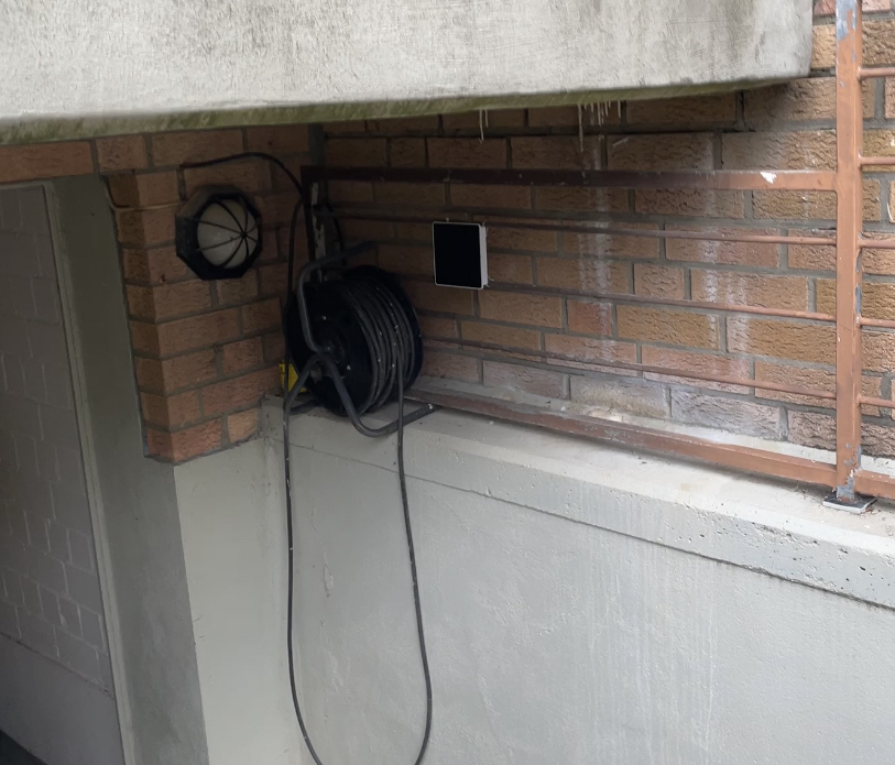
Use externally available GSM-2C clips and cable ties.
The 2-4 clips can be mounted by M4x8 Countersunk head screw to the Lobaro Solar Gateway.
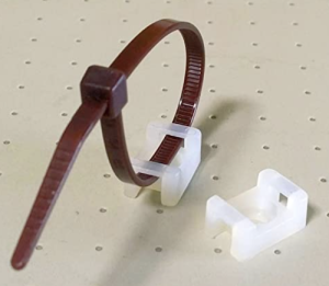
- GSM-2C Datasheet (GW Kabelbinder-Technik GmbH)
- Buy GSM-2C on Amazon (aprox. 5€ / 100 pcs.)
Example Mountings
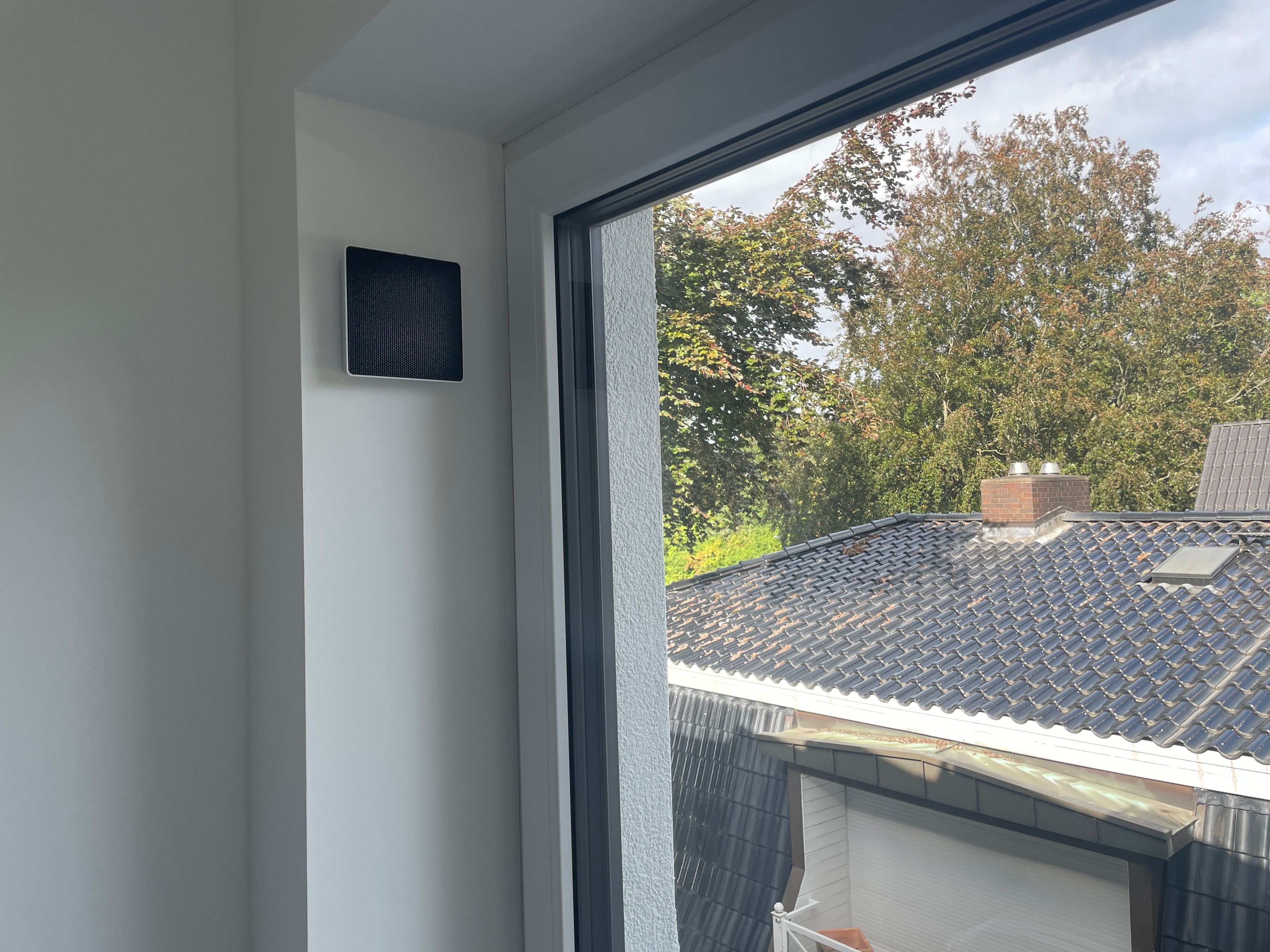
Indoor Near Window Mount
Housing attached using Hook & Loop Tape. Location good enough for multiple readings per day.
Outdoor mounting in the basement staircase
Housing attached using GSM-2C clips and cable ties. Location good enough for hourly readings.